Electric device with differential protection

A protection device and differential protection technology, applied in emergency protection devices, parts of protection switches, electrical components, etc., can solve problems such as failure to provide connecting combs through the bottom, breakage, etc.

Active Publication Date: 2013-01-16
SCHNEIDER ELECTRIC IND SAS
View PDF2 Cites 0 Cited by
  • Summary
  • Abstract
  • Description
  • Claims
  • Application Information

AI Technical Summary

Problems solved by technology

[0022] A drawback of this arrangement is that the output terminals are not arranged so that electrical connection can be made with the connection comb unless the teeth of the comb facing the output terminals of the circuit breaker part break
In addition, the realization of a differential protection device comprising two separate units requires additional actions by the user and it is not possible to provide this connection comb via the bottom

Method used


Image

  • Electric device with differential protection
  • Electric device with differential protection
  • Electric device with differential protection

Examples


Embodiment Construction

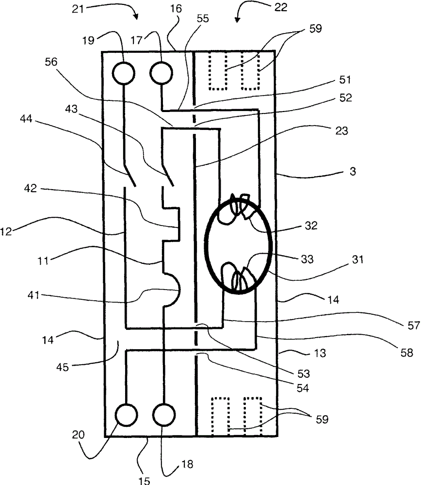
[0046] as attached Figure 5 As schematically shown in , an example of the differential protection of the present invention includes a phase circuit (phase circuit) 201 and a neutral circuit 202 in an enclosure 203 . The housing includes two main boards 204 , a first side board 205 and a second side board 206 . Each circuit extends between an input terminal 207 , 208 and an output terminal 209 , 210 . Input terminals 207 , 208 are provided on the second side plate 206 . The output terminals 209 , 210 are arranged for their part on the first side plate 205 .

[0047] The device includes a circuit breaking part 211 and a differential protection part 212 . The differential protection section is separated from the circuit breaker section by a bulkhead 213 which is substantially parallel to the main board 2104 and extends the entire length of the housing 203 .

[0048] In the differential protection part 212, a differential transformer (differential transformer) 221 is provided...


PUM


Abstract

The device has a differential protection part (212) including a differential transformer (221) equipped with windings (222, 223). Connecting wires (244, 245) connect the windings to a phase circuit (201) and a neutral circuit (202). A compartment (235) has a wall (241) parallel to lateral surfaces (205, 206) of a case (203) and equipped with bushings (242, 243). The connecting wires pass through a bushing (251) arranged on a partition (213) separating the protection part from a circuit-breaker part (211).

Description

technical field [0001] The invention relates to the field of electrical installations with differential protection, such as differential circuit breakers or differential switches, or other combinations of protection or control units such as contactors. [0002] In particular, the invention relates to electrical installations with modular differential protection, comprising: [0003] a phase circuit and a neutral circuit each extending between an input terminal and an output terminal, said terminals being electrically connectable by means of a connecting comb, [0004] a housing comprising two main boards, and first and second side boards on which input and output terminals are disposed, [0005] a circuit breaker section comprising a trip mechanism, a switch mounted on each circuit, an arc chute and a compartment comprising at least the switch and the arc chute, the compartment having a wall provided with at least a first through hole, [0006] a differential protection sect...

Claims


Application Information

Patent Timeline
Patent Type & Authority Patents(China)
IPC IPC(8): H01H83/14
CPCH01H71/002H01H71/025H01H83/226
Inventor 伯纳德·勒博尼古拉斯·伯纳德
Owner SCHNEIDER ELECTRIC IND SAS
Why Eureka
Try Eureka