Seal structure for tank periscopic lens

A technology of sealing structure and sight glass, used in telescopes, optics, instruments, etc., can solve the problems of large resistance torque and short service life of the peripheral sight glass, and achieve the effects of long service life, small resistance torque and convenient installation.

Inactive Publication Date: 2009-03-18
BEIJING JIAOTONG UNIV
View PDF0 Cites 2 Cited by
  • Summary
  • Abstract
  • Description
  • Claims
  • Application Information

AI Technical Summary

Problems solved by technology

[0003] In order to overcome the deficiencies of large resistance torque, non-zero leakage seal and short lifespan of the periscope mirror with felt sealing structure, the present invention provides a structure that not only has extremely small resistance torque and is easy to install, but also can achieve zero leakage, high reliability, long lasting

Method used


Image

  • Seal structure for tank periscopic lens
  • Seal structure for tank periscopic lens
  • Seal structure for tank periscopic lens

Examples


Embodiment Construction

[0015] The present invention will be further explained in conjunction with the drawings:

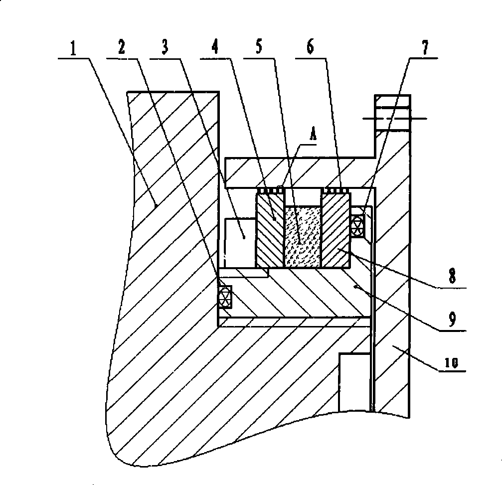
[0016] The sealing structure of the tank mirror, see figure 1 .

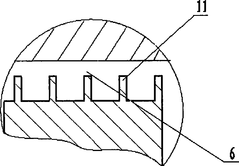
[0017] Put the first "O" ring 2 into the annular groove 12 on the small-diameter end of the non-magnetic sleeve 9, the second

[0018] The "O" ring 7 is inserted into the annular groove 13 on the inner surface of the large diameter end of the non-magnetic conductive sleeve 9;

[0019] Insert the right pole shoe 8, the permanent magnet 5 and the left pole shoe 4 from the small diameter end of the non-magnetic sleeve 9 in sequence, and use the screw connection of the nut 3 and the small diameter end of the non-magnetic sleeve 9 to lock the above three parts in the non-magnetic sleeve. On the magnetic sleeve 9, the non-magnetic sleeve 9 is threadedly connected with the azimuth shaft 1;

[0020] The upper reverse head 10 is sleeved on the right pole shoe 8 and the left pole shoe 4 assembled above, and forms a sealing gap 6, see f...


PUM


Abstract

The invention discloses a tank panoramic mirror sealing structure, relating to a magnetic liquid sealing structure, which respectively arranges a first O-shaped ring (2) and a second O-shaped ring (7) into two annular slots (12, 13) of a non-magnetic sleeve (9); mounting a right polar boot (8), a permanent magnet (5) and a left polar boot (4) from the small end of the non-magnetic sleeve (9); using a nut (3) to connect the screw of the small end of the non-magnetic sleeve (9) to lock the three elements on the non-magnetic sleeve (9), connecting the non-magnetic sleeve (9) and an direction shaft (1) via screws; sheathing an upper adverse head (10) on the right polar boot (8) and the left polar boot (4) and forming a sealing clearance (6); filling magnetic liquid into the sealing clearance (6) to form a tank panoramic mirror sealing structure. The tank panoramic mirror sealing structure has low resistance moment, simple installment, high reliability, long service life and the ability for realizing zero leakage.

Description

Technical field [0001] The invention relates to a magnetic liquid sealing structure, in particular to the sealing structure of a tank peripheral mirror. Background technique [0002] Tanks are mostly used in field operations, requiring all parts to work normally for a long time. Due to the large amount of dust and other impurities in the environment, in order to prevent external dust and impurities from entering the peripheral mirror, ensure the clarity and accuracy of the peripheral mirror , The use of felt to seal the passage between the movable part and the stationary part, the resistance torque during movement is large, the wear is fast, which leads to the weakening of the sealing effect and the short service life. Summary of the invention [0003] In order to overcome the shortcomings of large resistance torque, non-zero leakage sealing, and short life of the peripheral mirror using the felt sealing structure, the present invention provides a structure that not only has ext...

Claims


Application Information

Patent Timeline
Patent Type & Authority Applications(China)
IPC IPC(8): G02B23/00G02B23/16
Inventor 李德才董国强蔡玉强黄彦李强
Owner BEIJING JIAOTONG UNIV
Why Eureka
Try Eureka