
Micro optical fibre voltage sensor based on ring micro-cavity

A voltage sensor, annular microcavity technology, applied in the process of producing decorative surface effects, microstructure technology, microstructure devices, etc.

Inactive Publication Date: 2009-03-18
ZHONGBEI UNIV
View PDF0 Cites 10 Cited by
  • Summary
  • Abstract
  • Description
  • Claims
  • Application Information

AI Technical Summary

Problems solved by technology

This feature has not yet been applied in the field of micro sensors

Method used


Image

  • Micro optical fibre voltage sensor based on ring micro-cavity
  • Micro optical fibre voltage sensor based on ring micro-cavity
  • Micro optical fibre voltage sensor based on ring micro-cavity

Examples


Embodiment Construction

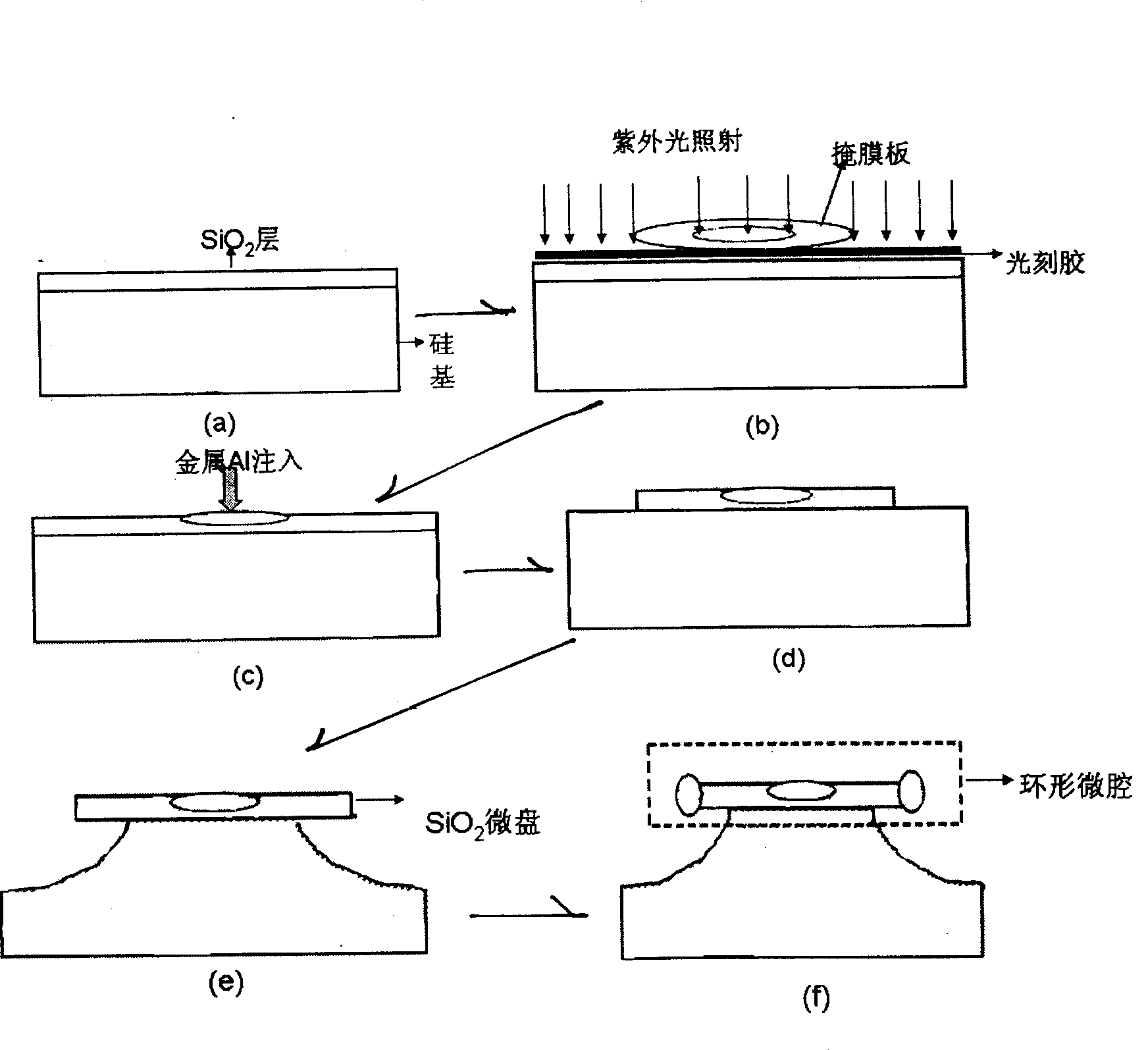
[0043] Such as figure 1 Shown schematically, a kind of micro-optical fiber voltage sensor based on the ring microcavity, the structure includes the planar ring microcavity 3 supported by the silicon column 5, and the tapered optical fiber 5 coupled with the planar ring microcavity 3, the middle part of the planar ring microcavity 3 An aluminum ohmic contact 2 is set on the microdisc, and two tungsten probes 1 are planted on the metal ohmic contact 2. The diameter of the annular microcavity in the above device is 60um--120um, the diameter of the ring is 5um--8um, and the silicon column The height of the tapered fiber is 30um--45um, the diameter of the tapered optical fiber is 1um--3um, the diameter of the ohmic contact is 20um--25um, the thickness is 0.1um, and the diameter of the probe is 10um--20um.

[0044] Such as figure 2 As shown, the processing method is, one, the making of annular microcavity,

[0045] 1. Thermally grow a silicon dioxide layer on a polished p-type hi...


PUM


Abstract

The invention relates to a microsensor designed by the MOEMS technique, in particular to a micro-optical fiber voltage sensor which is fabricated by utilizing a high Q annular microcavity and is based on the annular microcavity; the problem that the high Q annular microcavity can not be properly applied to sensors is solved. The micro-optical fiber voltage sensor comprises a plane annular microcavity supported by a silicon column and a conical optical fiber coupled with the plane annular microcavity, wherein, two tungsten electrode probes are planted on an aluminum ohmic contact which is arranged on a micro-disc of the middle part of the plane annular microcavity. The micro-optical fiber voltage sensor has the advantages that the gradually mature MEMS process technique is utilized, and the current physics knowledge is taken as the theoretical basis to develop the voltage sensors towards the direction of micromation and integration. The micro-optical fiber voltage sensor does not have the disadvantages of large volume, high power consumption, serious environmental influence, and the like, of the original optical fiber voltage sensors.

Description

technical field [0001] The invention relates to a micro-sensor designed by micro-opto-electromechanical system technology, in particular to a ring-shaped micro-cavity-based micro-optical fiber voltage sensor processed by a high-Q ring-shaped micro-cavity. Background technique [0002] Voltage sensing is an important application of optical fiber sensing. Research on optical fiber voltage sensors began in the 1970s. During years of development, various models and theories of optical fiber voltage sensors have been proposed. There are two types: functional and non-functional. Functional fiber optic voltage sensors mainly use linear piezoelectric elements or electrostrictive elements as phase modulators. The non-functional fiber optic voltage sensor uses the linear electro-optic effect of electro-optic crystals to sense voltage. [0003] The earliest fiber optic voltage sensor is the Fabry-Pelot fiber optic voltage sensor. After nearly 30 years of development, the fiber optic ...

Claims


Application Information

Patent Timeline
Patent Type & Authority Applications(China)
IPC IPC(8): B81C1/00
Inventor 闫树斌张文栋熊继军姜国庆王少辉严英占王宝花吉喆任小红
Owner ZHONGBEI UNIV
Learn More