
Skin grafting operation quick partitioning placement device

A surgical and rapid technology, applied in the field of medical equipment, can solve the problems of long operation time, time-consuming doctors, and irregular arrangement of "pin" characters, etc., and achieve the effect of shortening operation time and reducing operation intensity

Inactive Publication Date: 2010-06-09
SHANGHAI JIAO TONG UNIV
View PDF7 Cites 0 Cited by
  • Summary
  • Abstract
  • Description
  • Claims
  • Application Information

AI Technical Summary

Problems solved by technology

However, postage stamp skin grafting also has many disadvantages: 1. More surgical personnel are required, because generally there are more postage stamps, in order to shorten the operation time as much as possible, it often needs as many people as possible to "post stamps" at the same time; Waste of human resources; 2. Even so, the operation time is still long
3. Due to objective factors such as irregular or uneven wounds, as well as subjective factors such as fatigue caused by the operator's long-term work, the arrangement of the character "pin" is irregular, and the postoperative scar is heavy, which affects the recovery of function and appearance.
[0004] After searching the literature of the prior art, it was found that the utility model patent "Skin Cutting and Grafting Machine" with the patent number of 200520023076.2 designed a device for cutting the skin into several small pieces, but the small pieces cut by the device need to be cut one by one by the doctor. Clipping and implanting one by one, it takes a lot of time for doctors
[0005] Patent No. 92245105.2 is a utility model patent "Small Skin Grafting Device", which can take and drop several small skins at the same time through positive and negative air pressure, and expand the distance between small skins through a square distance expander, but this device does not mention skin The division of the slices, the spacing between the slices is even, the layout of the slices is parallel, and the layout of the "pin" shape cannot be realized

Method used


Image

  • Skin grafting operation quick partitioning placement device
  • Skin grafting operation quick partitioning placement device
  • Skin grafting operation quick partitioning placement device

Examples


Embodiment Construction

[0022] The embodiments of the present invention are described in detail below in conjunction with the accompanying drawings: this embodiment is implemented on the premise of the technical solution of the present invention, and detailed implementation methods and specific operating procedures are provided, but the protection scope of the present invention is not limited to the following the described embodiment.

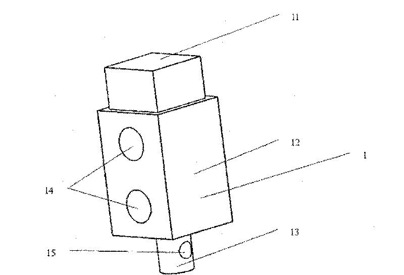
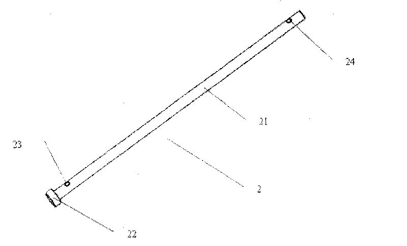
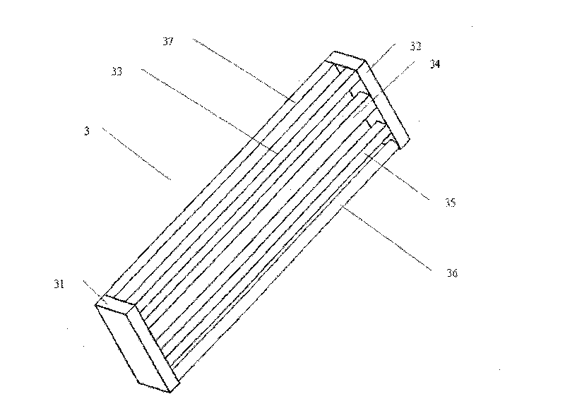
[0023] Such as figure 1 , figure 2 , image 3 , Figure 4 As shown, this embodiment includes five parts: a unit block 1 , a connecting guide rod 2 , a left connecting slot plate 3 , a right connecting slot plate 4 , and a connecting cord 5 .

[0024] Such as figure 1 As shown, the unit block 1 includes a unit upper part 11 for skin cutting and placement, a unit middle part 12 with two connecting through holes 14, and a unit lower part 13 with a connecting through hole 15. These three parts are formed from top to bottom A whole.

[0025] Such as figure 2 As sh...


PUM


Abstract

The invention discloses a fast blocking-positioning device of skin grafting in the technical field of medical appliance, wherein, a connecting leader goes through the connecting through holes of unitblocks and skewers a plurality of unit blocks into one line; the cylinder station of the connecting leader is inserted in the gap between the baffles in front of the left connecting trough plate and the gap between the front baffle and the rear baffle, and the right side of the connecting leader goes through the gap between the baffles in front of the right connection trough plate; after going through a connecting through hole of the unit block and being knotted, the connecting flexible cord goes through the connecting through hole of the next unit block and is knotted, and the two ends of thehorizontal connecting flexible cord are respectively sheathed on the vertical leaders of the right and left connecting trough planes; after going through the left and right vertical connecting holesrespectively and being knotted, two vertical connecting flexible cords go through the left and right vertical connecting holes of the next connecting leader and are knotted. The invention facilitateshealthy skin to be in the shape of Chinese word 'PIN', a plurality of healthy skins are implanted at the same time, the time of skin grafting is reduced, and work intensity is reduced.

Description

technical field [0001] The invention relates to a device in the technical field of medical instruments, in particular to a device for rapid block layout of skin implant surgery. Background technique [0002] Clinically, patients with large deep second-degree or third-degree burns, and patients with full-thickness skin defects or necrosis after trauma often require surgical skin grafting to achieve wound healing. However, these patients have little healthy skin left and need skin grafting The wound surface is large, and the biggest problem in surgical treatment is the contradiction between "supply" and "demand" of autologous skin. [0003] At present, the commonly used skin grafting methods in clinic can be divided into: 1. According to the thickness of the skin graft, it can be divided into: blade-thickness skin graft, medium-thickness skin graft, full-thickness skin graft and skin graft with subdermal vascular network ; 2. According to the shape of the skin graft, it can b...

Claims


Application Information

Patent Timeline
Patent Type & Authority Patents(China)
IPC IPC(8): A61B17/322
Inventor 谢叻庄小龙方勇赖芸赵志球
Owner SHANGHAI JIAO TONG UNIV
Learn More