Conical rolling device

A spheronizing machine and cone technology, which is applied in the field of new machinery and equipment, can solve the problems of inability to roll conical parts and so on.

Inactive Publication Date: 2009-02-11
赵春惠
View PDF0 Cites 4 Cited by
  • Summary
  • Abstract
  • Description
  • Claims
  • Application Information

AI Technical Summary

Problems solved by technology

[0002] Conical parts cannot be rolled on existing cylindrical spheronizers

Method used


Image

  • Conical rolling device
  • Conical rolling device

Examples


Embodiment Construction

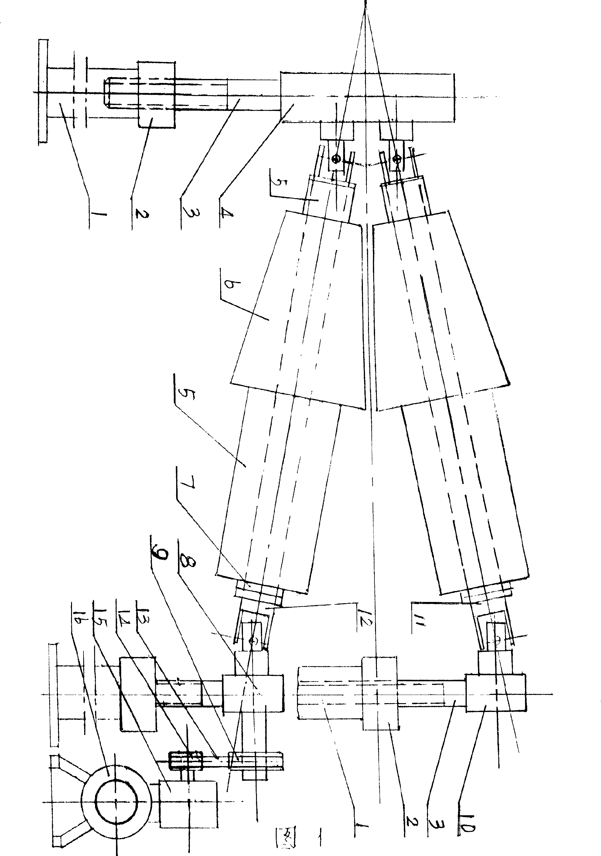
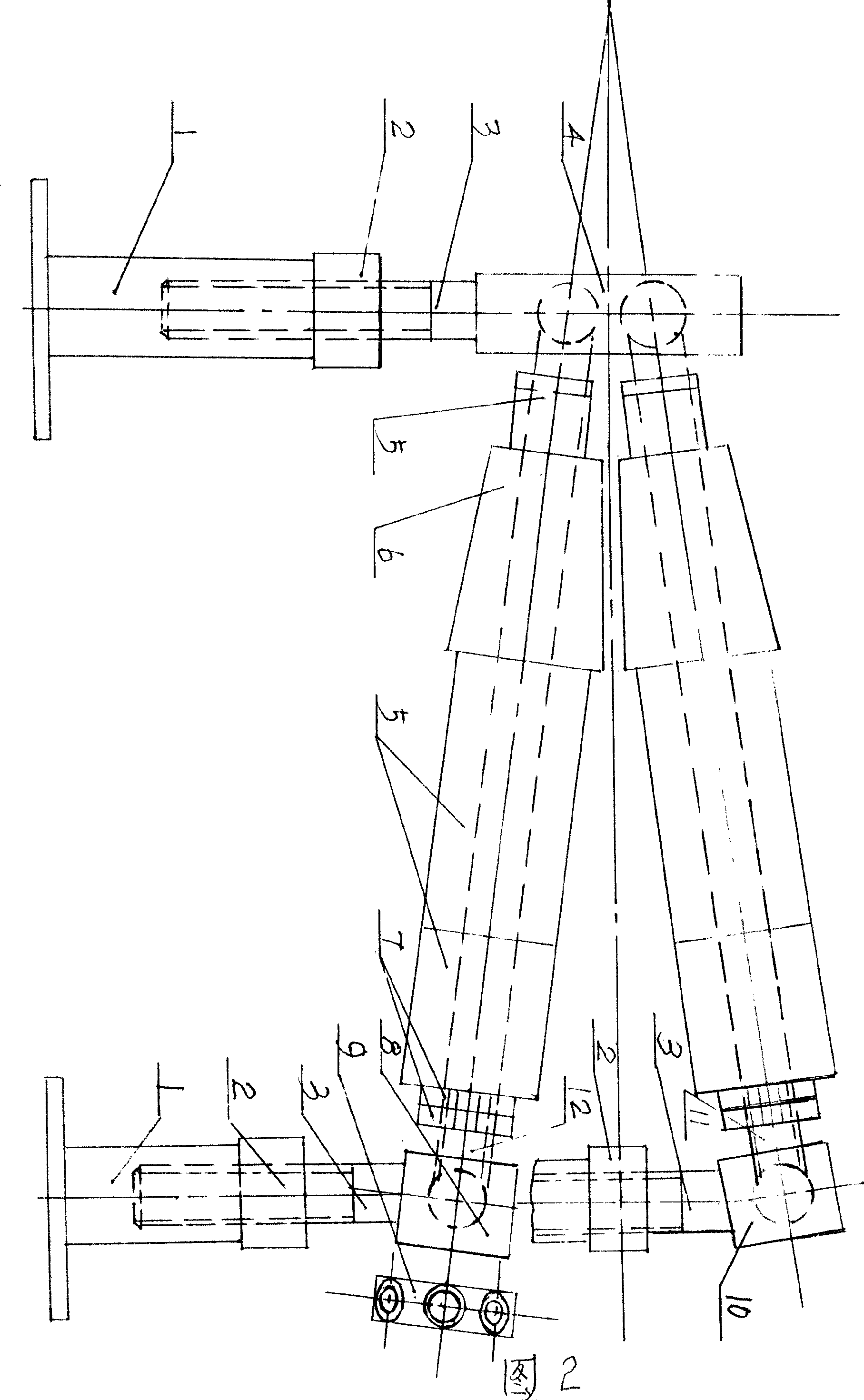
[0009] Attached drawing 1. The main body of the electric-driven conical rolling machine consists of supporting legs 1, screw nut 2, screw 3, supporting disc 4, pad cover 5, tapered roller 6, lock nut 7, lower support sleeve 8, upper support Cover 10, upper roller 11, lower roller 12 form. Power system is made up of large pulley 9, V-belt 13, small pulley 14, worm gear reducer 15, motor 16 several parts. Three rollers are installed on the support disc 4 and the upper support sleeve 10 and the lower support sleeve 8, and their connection mode is to utilize a universal joint. Both ends of the three shafts are integrated with one end of the universal joint, and the other end of the universal joint is fixedly connected with the upper and lower support sleeves of the support disc respectively. The extended line of the central line of one upper roller and two lower rollers intersects at a point, which is called a vertex. The end near the apex is called the apex, and the end farther...


PUM


Abstract

The invention discloses novel mechanical equipment which is a conical rounding machine and can roll and manufacture steel plates into cone-shaped parts. The invention designs two conical rounding machines which are electric power driven conical rounding machines and a manual power driven conical rounding machine. The integral structure of the conical rounding machines in the two forms consists of supporting legs, master screws, lead screw supporting circular discs, cushion covers, conical rollers, locknuts, upper rollers and lower rollers and upper supporting sleeves and lower supporting sleeves, wherein, three rollers are placed between the supporting disc and the upper supporting sleeves and the lower supporting sleeves and are connected to cause the extended lines of the central lines of one upper roller and two lower rollers to intersect at one point; each roller is respectively provided with a conical roller arranged in a middle position and the cushion covers are arranged at the left and right sides of the roller and are locked on the roller by the locknuts. A dynamic system of the electric power driven rounding machine consists of a motor, a turbine reducer, a triangular belt, a big belt pulley and a small belt pulley. In the manual power driven rounding machine, only one hand wheel is arranged at the end of the lower roller, and gaps of the upper rollers and the lower rollers are fed with blanked fan-shaped sheet materials; when the power is transmitted onto the rollers, the rollers rotate continuously and the sheet materials become conical parts.

Description

1. Technical field [0001] The present invention relates to a new mechanical equipment, that is, a cone rolling machine. It can roll conical parts with different tapers. 2. Background technology: [0002] Conical parts cannot be rolled on existing cylindrical spheronizers. Sometimes the upper roller is placed in an inclined position by using a cylindrical spheronizer, and only non-standard, weirdly shaped parts that look like circles but not circles, and that look like cones but not cones can only be rolled out. Three invention contents: [0003] The purpose of the present invention is to provide a reasonable, novel and practical technical equipment capable of rolling standard conical parts. There are two types of design: the electric-driven cone rolling machine and the manual-driven cone rolling machine. Now introduce them respectively: [0004] 1. The electric drag cone rolling machine is composed of supporting legs, screw nuts, screw support discs, cushion sleeves, t...

Claims


Application Information

Patent Timeline
Patent Type & Authority Applications(China)
IPC IPC(8): B21D5/14
Inventor 赵春惠
Owner 赵春惠
Why Eureka
Try Eureka