Conveying and processing device of fluid resin

A technology for processing equipment and fluid resin, which is applied in the field of fluid resin transportation and processing equipment, and can solve problems such as the cylinder cannot be pulled, the piston is too large, and the air cannot be completely isolated.

Inactive Publication Date: 2009-02-04
季伯青
View PDF0 Cites 0 Cited by
  • Summary
  • Abstract
  • Description
  • Claims
  • Application Information

AI Technical Summary

Problems solved by technology

[0002] At present, when using unsaturated polyester, epoxy resin and other fluid resins to process decorations, handicrafts and clothing accessories, it is usually injected into the mold with a syringe or a piston machine similar to a syringe after the materials are prepared. The sealing device is set on the piston, which is in close contact with the cavity to form a seal. In this way, first, the air cannot be completely isolated, and it is easy to enter the syringe or piston machine, causing the resin to oxidize and form a sticky layer on the cavity wall, causing the syringe to It cannot be pulled, or the piston is worn out, and the sealing ring is damaged. It needs to be replaced or cleaned frequently, which not only wastes raw materials and utensils, but also makes the production efficiency low; If the piston is too large, it will cause deviation and affect product quality

Method used


Image

  • Conveying and processing device of fluid resin

Examples


Embodiment Construction

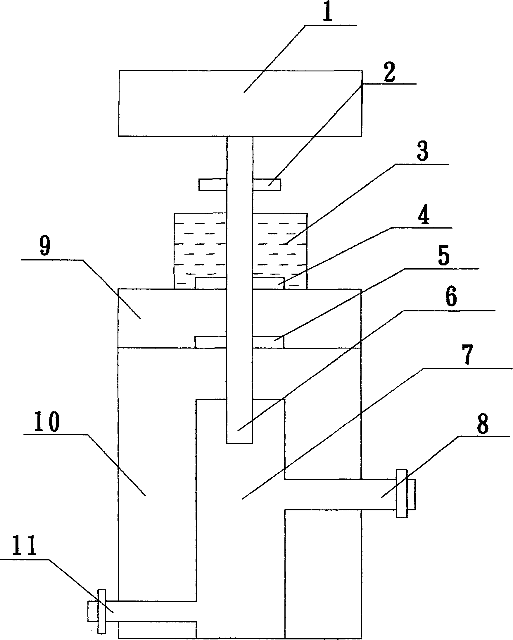
[0012] refer to figure 1 , the conveying and processing equipment of the fluid resin includes a body 10, a cylinder 1, a sealed oil tank 3, a seal 4, a seal 5, a push rod 6, a vacuum raw material chamber 7, a feed port 11, a discharge port 8, an adjustment limit Card 2, cover plate 9; the cylinder 1 is located at the top of the body 10, the sealed oil tank 3 is located between the body 10 and the cylinder 1, the cover plate 9 is located between the sealed oil tank 3 and the body 10, and is tightly closed with the body 10, and the vacuum raw material chamber 7 Set in the body 10; the cylinder 1 is connected to one side of the push rod 6, the push rod 6 passes through the sealed oil tank 3, and the other side is set in the vacuum raw material chamber 7, and the push rod 6 can be used under the action of the cylinder 1. The sealed oil tank 3 and the vacuum raw material chamber 7 move up and down; the seal 4 and the seal 5 are set on the push rod 6, the seal 4 is fixed at the join...


PUM


Abstract

The invention relates to a device for transmitting and processing fluent resin. The device comprises a machine body, a cylinder, a sealed oil box, a plurality of sealing elements, a push rod, a vacuum raw material cavity, a feeding hole, a discharge hole, a cover board and an adjustment spacing card, and the vacuum raw material cavity is arranged in the machine body; one side of the push rod is connected with the cylinder, and the other side of the push rod is located in the vacuum raw material cavity; the machine body is opened with the feeding hole and the discharging hole, and the feeding hole and the discharging hole are communicated with the vacuum raw material cavity; the sealed oil box is arranged outside the machine body, and the push rod goes through the sealed oil box; the cover board is arranged between the sealed oil box and the machine body and is jointed with the machine body tightly; the adjustment spacing card is arranged on the push rod and is used for output by fixed position and fixed amount. By adopting the sealed oil box and the vacuum raw material cavity, the place that one side of the push rod touches the raw material is in the state of vacuum, oxidation can not happen on the resin, the push rod can not form ropiness, and the push rod can be replaced at any time according to the amount of the dosage, and the adjustment spacing card can control the output preciously, thus facilitating the products to satisfy the requirements of quality and realize mechanized production.

Description

Technical field [0001] The invention relates to a conveying and processing equipment of fluid resin. Background technique [0002] At present, when using unsaturated polyester, epoxy resin and other fluid resins to process decorations, handicrafts and clothing accessories, it is usually injected into the mold with a syringe or a piston machine similar to a syringe after the materials are prepared. The sealing device is set on the piston, which is in close contact with the cavity to form a seal. In this way, first, the air cannot be completely isolated, and it is easy to enter the syringe or piston machine, causing the resin to oxidize and form a sticky layer on the cavity wall, causing the syringe to It cannot be pulled, or the piston is worn out, and the sealing ring is damaged. It needs to be replaced or cleaned frequently, which not only wastes raw materials and utensils, but also makes the production efficiency low; If the piston is too large, it will cause deviation an...

Claims


Application Information

Patent Timeline
Patent Type & Authority Applications(China)
IPC IPC(8): B29C31/04
Inventor 季伯青
Owner 季伯青
Why Eureka
Try Eureka