Plug used in boring machine
A piercing machine and punch technology, applied in metal rolling, manufacturing tools, mandrels, etc., can solve the problem of easy occurrence of melting loss, and achieve the effect of preventing melting loss and reducing the amount of cutting changes.
- Summary
- Abstract
- Description
- Claims
- Application Information
AI Technical Summary
Problems solved by technology
Method used
Image

Examples
Embodiment 1
[0075] use Figure 9 , Figure 10 and the punches of the shapes shown in Table 1, the billets were pierced and rolled, and the life of each punch was investigated.
[0076] [Table 1]
[0077]
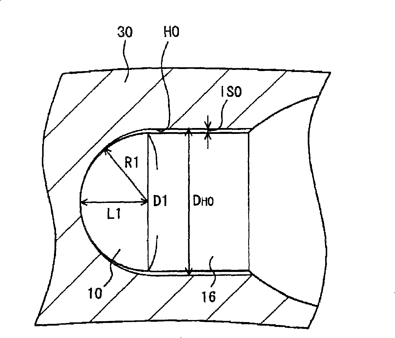
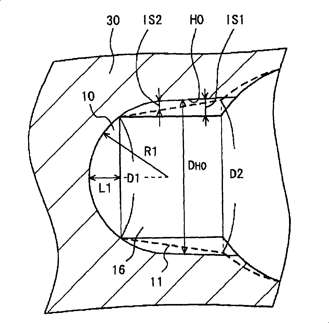
[0078] The punches of test numbers 1 to 15 and 20 to 24 in Table 1 were formed as Figure 9 In the shape shown, the punches of test numbers 16 to 19 were formed as Figure 10 the shape shown. The symbols (dimensions) of items 7 to 19 in Table 1 and Figure 9 and Figure 10 The notations in are used in pairs. The material of each punch is 1.5% Cr-3% Ni steel (SNCM616 in JIS standard).
[0079] The pierced and rolled billet was formed into a round billet of SUS304 steel with a diameter of 70 mm and an axial length of 400 mm. The billet heated to 1200° C. was pierced and rolled by a piercer equipped with a punch of each test number to form a hollow billet tube with an outer diameter of 76 mm and a wall thickness of 6 mm. The conditions of the punching machine are shown in Table...
Embodiment 2
[0090] The punches of test numbers 20 to 22 did not have a corner radius Rc, but the other shapes and dimensions were the same as the punches of test numbers 7 to 9. Specifically, the punch of test number 20 has the same shape as the punch of test number 7 except for the corner radius Rc. Similarly, the punch of Test No. 21 and Test No. 8, and the punch of Test No. 22 and Test No. 9 have the same shape and dimension except for the corner radius Rc.
[0091] As a result of investigation in Example 1, the number of punches of test numbers 20 to 22 that could be rolled was three or more, similarly to test numbers 7 to 9 . Therefore, in order to investigate the effect of the corner radius, the number of punches that can be rolled was further investigated for the punches of test numbers 7 to 9 and 20 to 22.
[0092] As a result of the investigation, the punches of test numbers 20 to 22 that did not have a corner radius Rc all had melting loss at the adjacent part of the front end ...
Embodiment 3
[0094] The relationship between the spherical shape of the tip portion and the occurrence of melting loss was investigated. Specifically, the number of punches that can be rolled was investigated for punches of test numbers 7 and 11, 8 and 12, and 9 and 13 in which the taper half-angle α was substantially the same and L1 / R1 was different. As a result, the number of punches that can be rolled was four for each punch. Therefore, for these punches, modified cutting was performed in the axial direction until the melted part disappeared, and the modified cutting amount of each punch was investigated. Specifically, the punch was changed and cut by 0.5 mm in the axial direction, and it was visually judged whether or not the melted part remained after the changed cutting. In the case of residual, and then modify the cutting 0.5mm in the axial direction. Table 3 shows the results of the investigation.
[0095] [table 3]
[0096] Test No.
L1 / R1
Change cutting amount...
PUM
 Abstract
Description
Claims
Application Information
 - R&D
- Intellectual Property
- Life Sciences
- Materials
- Tech Scout
- Unparalleled Data Quality
- Higher Quality Content
- 60% Fewer Hallucinations
Browse by: Latest US Patents, China's latest patents, Technical Efficacy Thesaurus, Application Domain, Technology Topic, Popular Technical Reports.
© 2025 PatSnap. All rights reserved.Legal|Privacy policy|Modern Slavery Act Transparency Statement|Sitemap|About US| Contact US: help@patsnap.com