
Rotary drive device and image forming apparatus

A technology of rotary drive and image, applied in the direction of transmission, gear transmission, electromechanical device, etc., it can solve the problems of increased rotary resistance, wear of the planetary gear or jamming, etc., to achieve a large reduction ratio and avoid wear or jamming. , space saving effect

Active Publication Date: 2009-01-14
RICOH KK
View PDF3 Cites 10 Cited by
  • Summary
  • Abstract
  • Description
  • Claims
  • Application Information

AI Technical Summary

Problems solved by technology

If the backlash in the normal direction changes in each part, the rotation resistance will increase, and wear or seizure will occur on the carrier, etc., so that the above structure cannot be adopted.

Method used


Image

  • Rotary drive device and image forming apparatus
  • Rotary drive device and image forming apparatus
  • Rotary drive device and image forming apparatus

Examples


Embodiment Construction

[0079] Hereinafter, embodiments of the rotary drive device and the image forming apparatus according to the present invention will be described in detail with reference to the drawings. In the following embodiments, various limitations are made to the constituent elements, types, combinations, shapes, relative arrangements, etc., but, These are merely examples, and the present invention is not limited thereto.

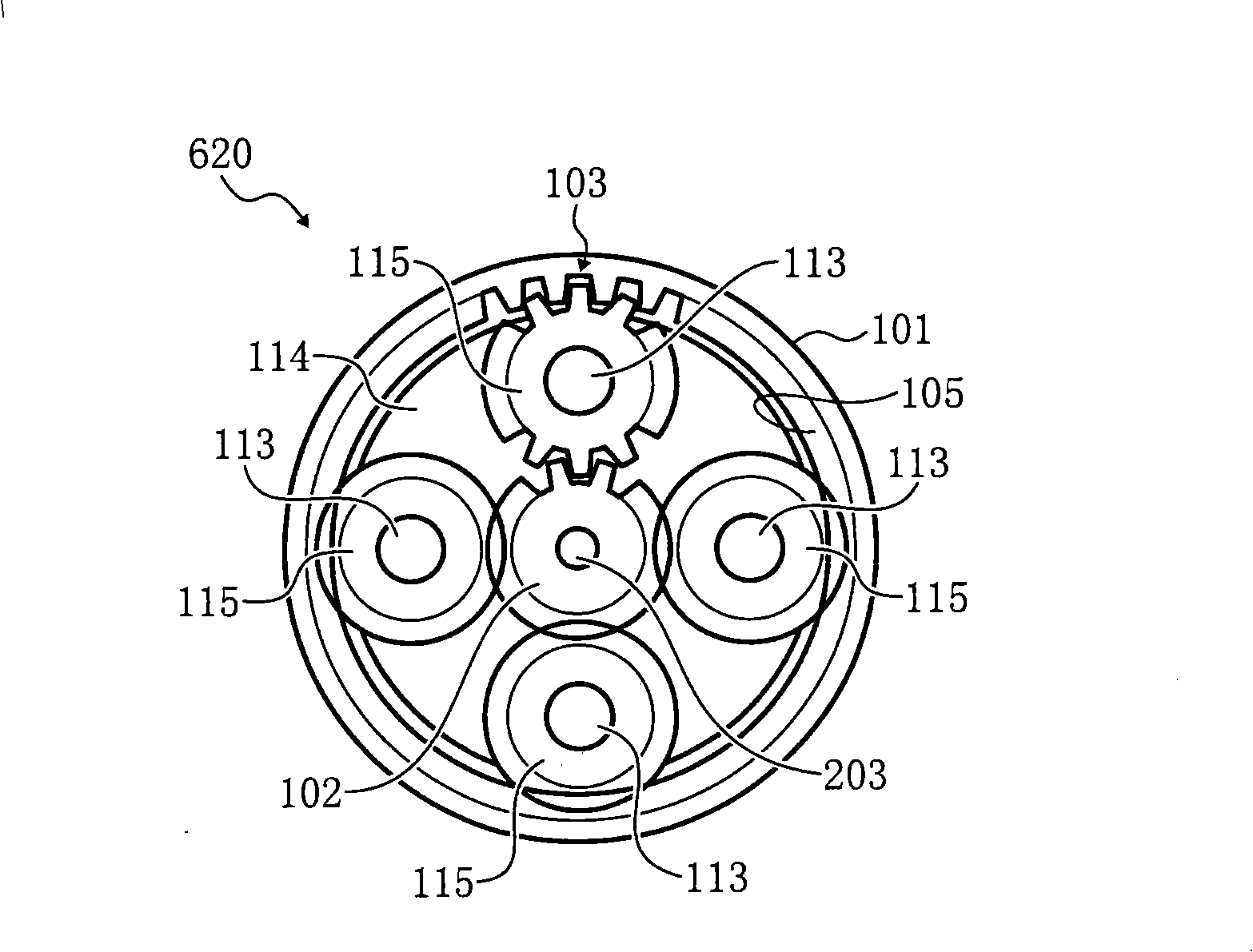
[0080] Figure 1-Figure 4 It shows the rotary driving device related to the first embodiment of the present invention, Fig. 5- Figure 7 Representing the rotary driving device related to the second embodiment of the present invention, Fig. 8 and Figure 9 An embodiment of an image forming apparatus equipped with the rotary drive device according to the first embodiment or the second embodiment is shown.

[0081] [First Embodiment]

[0082] The rotary driving device of the first embodiment is as figure 1 As shown, a planetary gear mechanism 100 , a motor 200 and a f...


PUM


Abstract

The invention relates to a rotary drive device and image forming apparatus, providing a rotary drive device with excellent assembly performance, excellent maintenance performance, increased accuracy of a sensor, increased load resistance, comprising a motor (200) including a rotary shaft (203); an outer gear (101), fixed on a case (202) of the motor (202); a plurality of planetary gear mechanisms (100), using the outer gear (101) as a common outer gear, decelerating a rotation output of the motor (200); an output shaft (117) transmitting the decelerated rotation output of the motor to an outside of the rotary drive device; a rotation position detector (300) detecting a rotation position of the output shaft (117). The motor (200), the planetary gear mechanism (100), and the rotation position detector (300) are combined into a single integrated unit and aligned in an axial direction of the rotary shaft (203) of the motor (200).

Description

technical field [0001] The present invention relates to a rotary drive device and an image forming device. Background technique [0002] Conventionally, there is an electrophotographic image forming apparatus that supports color images. [0003] The image forming device arranges a photoreceptor along the intermediate transfer belt, forms color-separated toner images of each color (including black) on the photoreceptor, arranges a primary transfer roller opposite the photoreceptor, and sandwiches the intermediate transfer roller. The toner image on the photoreceptor is transferred to the intermediate transfer belt, and the toner images of each color are superimposed on the intermediate transfer belt to form a color toner image. The above-mentioned color toner image is transferred to the secondary transfer roller. The toner image is transferred on the recording paper, and then the toner image is fixed on the recording paper by heat and pressure through a fixing device. [00...

Claims


Application Information

Patent Timeline
Patent Type & Authority Applications(China)
IPC IPC(8): G03G15/00G05D3/12H02K7/116F16H1/32
Inventor 上原拓也江原让三浦洋平邑田拓也
Owner RICOH KK
Learn More