
Device for the removal of thrombi from blood vessels

A blood vessel and thrombus technology, applied in the field of devices for removing thrombus from blood vessels, can solve the problems of easy disturbance and high design requirements

Inactive Publication Date: 2009-01-07
PHENOX
View PDF3 Cites 33 Cited by
  • Summary
  • Abstract
  • Description
  • Claims
  • Application Information

AI Technical Summary

Problems solved by technology

However, a drawback associated with this device is that in order to cool the capture arms before they are released into the bloodstream and thus keep them below the transition temperature, it must be moved past the thrombus in a secondary conduit producing a cooling effect, or the heating system must be placed in Catheter interior with capture arms to allow access to transition temperature when thrombus is reached
Not only is the design of this configuration demanding and thus prone to perturbation, but the physical scale of the device precludes the treatment of vessels with particularly small lumens

Method used


Image

  • Device for the removal of thrombi from blood vessels
  • Device for the removal of thrombi from blood vessels
  • Device for the removal of thrombi from blood vessels

Examples


Embodiment Construction

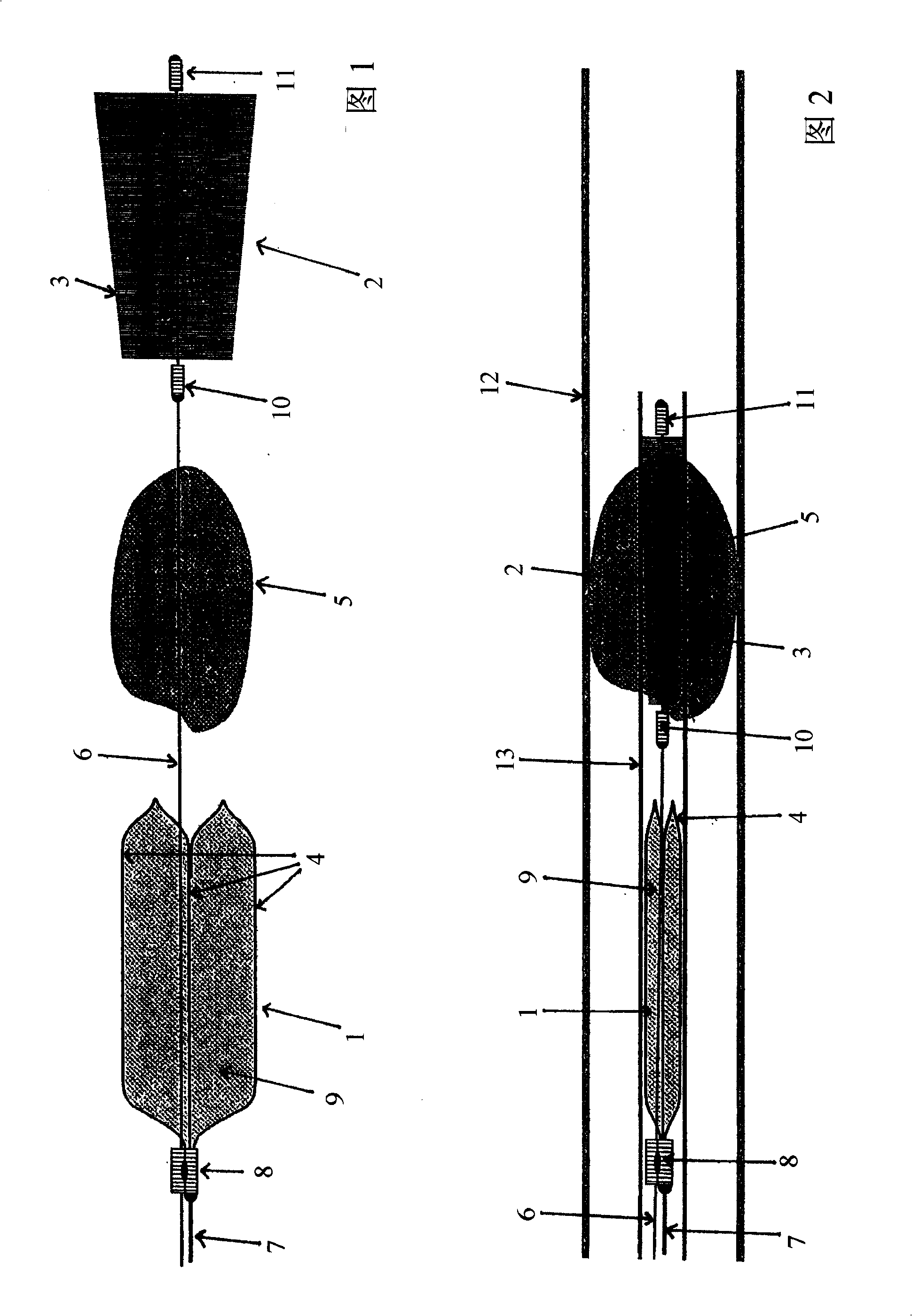
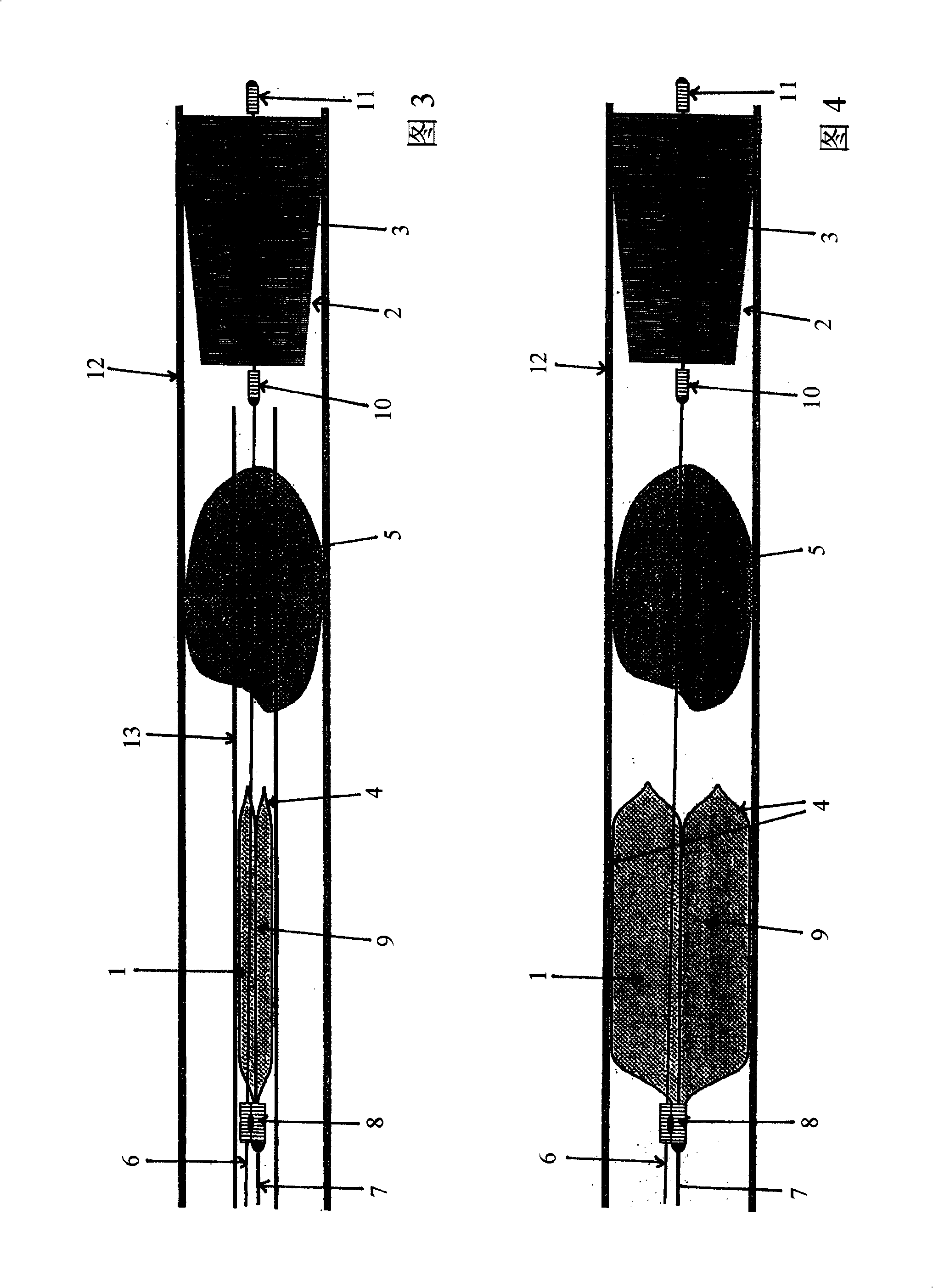
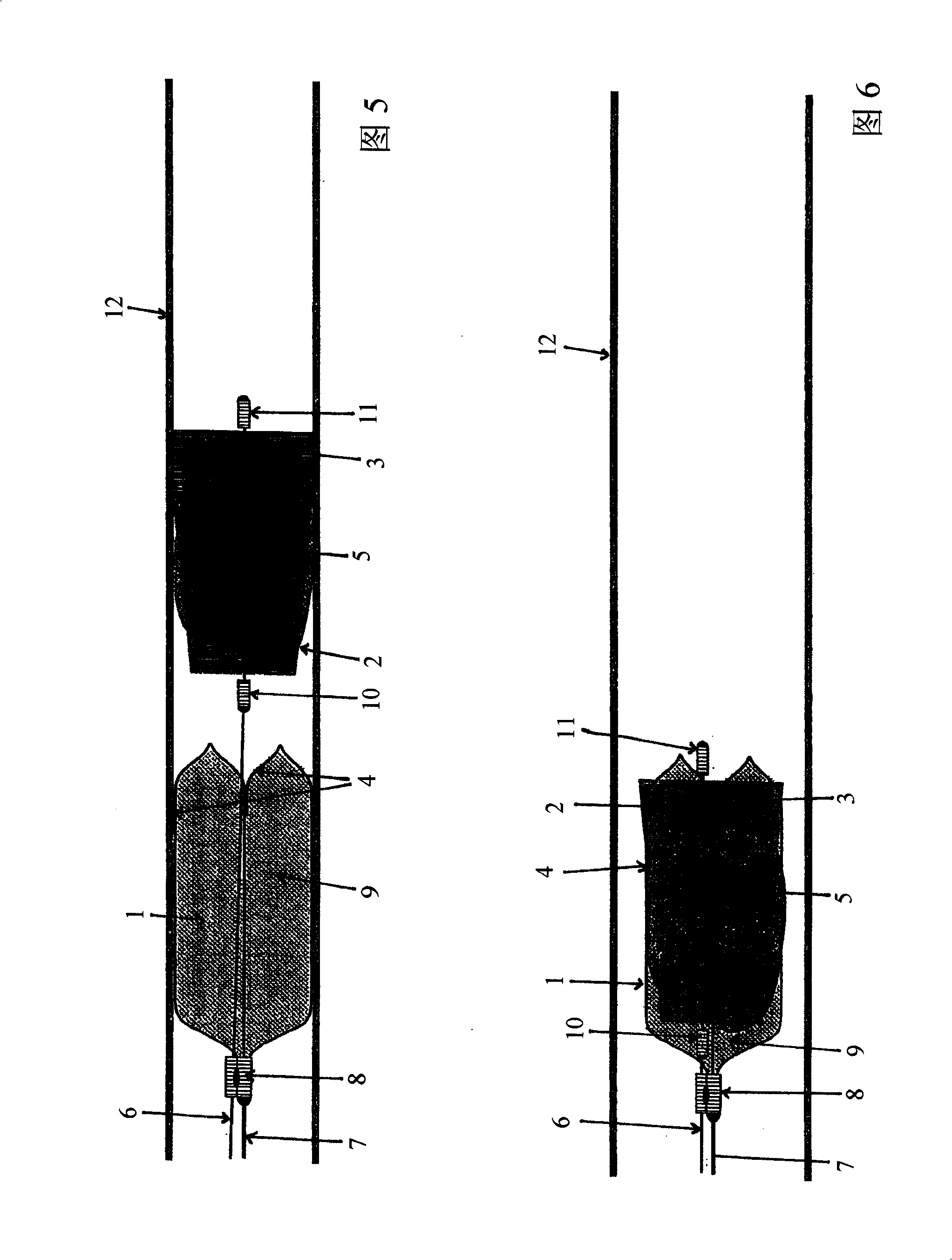
[0080] Figure 1 is a diagram of a first embodiment of the invention shown as a side view. The device has in particular a cage-like structure 1 and a distal element 2 as main components. Fibers 3 protrude radially outwards from the distal element 2 . The cage structure 1 consists of struts 4, the main part of which extends in the longitudinal direction. The device is used to capture a thrombus 5, initially, with the help of the distal element 2 and the fibers 3 protruding therefrom, by moving the distal element 2 backwards in the proximal direction and finally maneuvering said thrombus into the cage In structure 1,. In the side views shown here, proximal always means to the left and far to the right. The distal element 2 and the cage structure 1 are movable by independent guide wires 6 and 7 . The cage-like structure 1 converges at its proximal end centrally in a sleeve 8 to which a guide wire 7 for the cage-like structure 1 is secured, while a guide wire 6 for the distal e...


PUM


Abstract

The invention relates to an assembly comprising a support (1, 3, 4) for intervertebral prostheses and intervertebral prostheses (2) that are provided with different widths and are composed of two final plates (21, 22) with a ventral flange (23, 24) and an intermediate joint core (20). The support (1, 3, 4) is equipped with a base plate (10, 30, 40) which encompasses holes (12, 32, 42) for accommodating one of the intervertebral prostheses (2) and is larger than the maximum width of the intervertebral prostheses (2). A couple of steps (17) are embodied on at least one longitudinal edge (13) of the hole (12, 32, 42).; The facing sides (18) of said couple of steps (17) are disposed at a specific distance from each other so as to center the flange (24) of an intervertebral prosthesis (2) that is inserted into the hole (12, 32, 42), thus making it possible to insert intervertebral prostheses (2) having different widths into the holes (12, 32, 42) and retain the same in a centered position in the holes (12, 32, 42) regardless of the actual width thereof.

Description

technical field [0001] The present invention relates to a device for removing foreign bodies and thrombi from body cavities and blood vessels using at least one guide wire with a distal element. Background technique [0002] Thromboembolic diseases such as cardiac infarction, pulmonary embolism, peripheral thrombosis, organ embolism, etc., are typically caused by thromboembolism (hereinafter simply referred to as thrombus or thrombus), that is, the formation of a viscoelastic blood clot in a blood vessel that it completely or partially occludes , which includes platelets, fibrin, coagulation factors, etc. Blockage of an organ's arteries also disrupts the supply of oxygen and nutrients to the involved tissues. Disturbances of functional metabolism associated with loss of function are followed by disturbances of structural metabolism, leading to destruction of the relevant tissue (infarction). The organs most often affected in this way are the heart and brain. However, the ...

Claims


Application Information

Patent Timeline
IPC IPC(8): A61B17/22
CPCA61B2017/22038A61B2017/22034A61B2019/547A61B2017/2215A61B17/221A61B2010/0216A61B2090/397
Inventor R·汉内斯曼纽尔·施奈德霍格·普拉希特E·米洛斯拉夫斯基H·蒂斯塔特
Owner PHENOX
Learn More