Compressor
A technology of compressor and compressing space, applied in the field of compressors, can solve the problems of increasing blade processing cost and difficult processing, and achieve the effects of low cost, improved workability, and reduced cost
- Summary
- Abstract
- Description
- Claims
- Application Information
AI Technical Summary
Problems solved by technology
Method used
Image

Examples
Embodiment 1
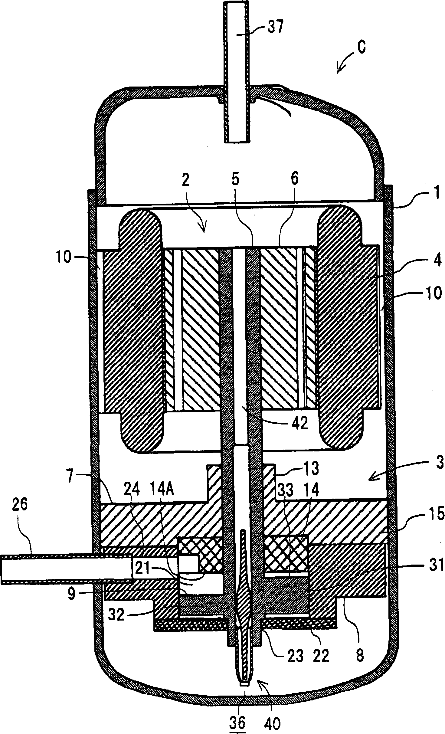
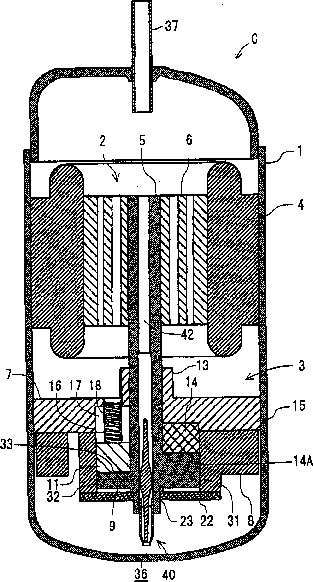
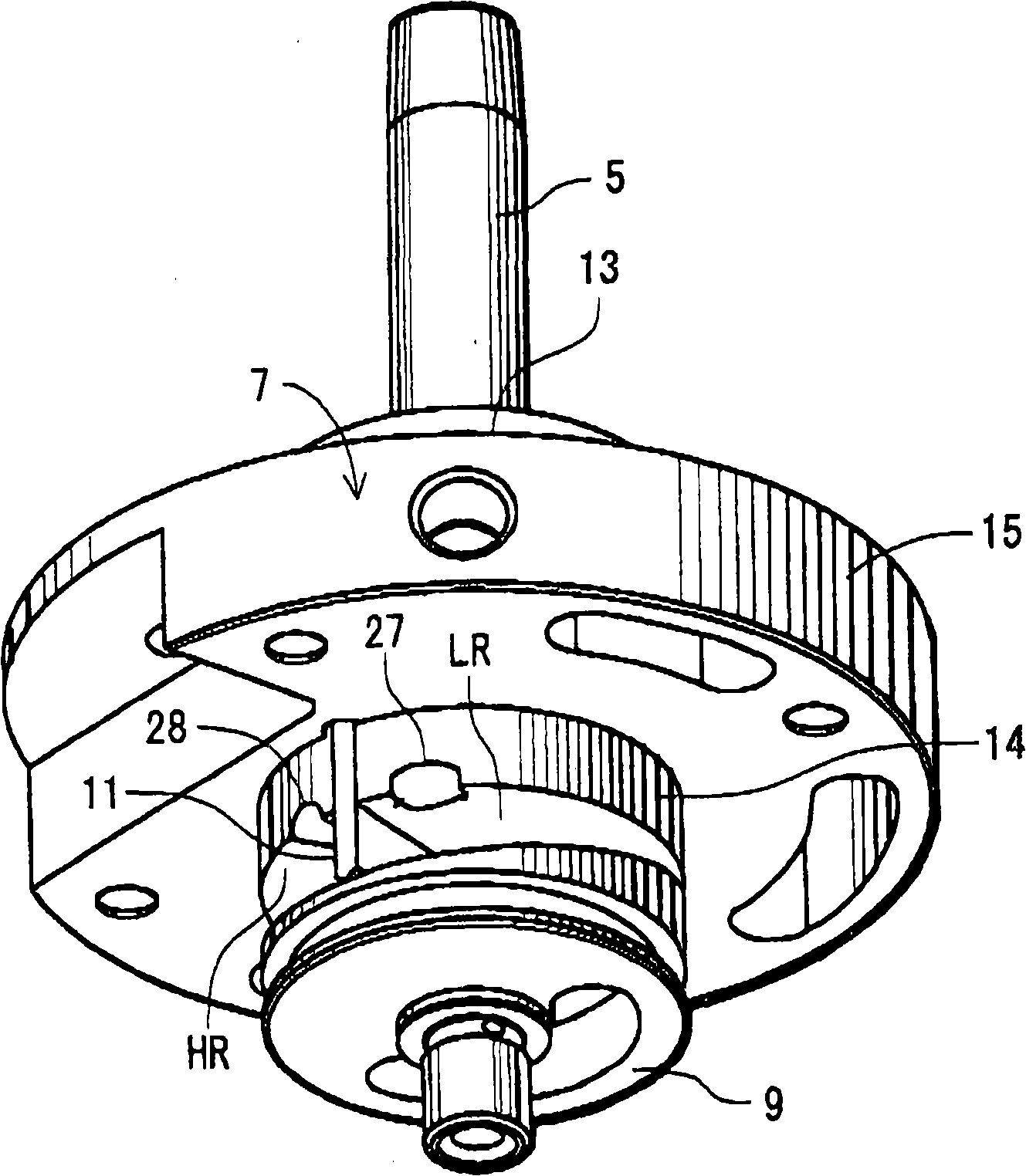
[0064] figure 1 A longitudinal sectional side view of a compressor C showing a first embodiment of the present invention, figure 2 represents another longitudinal profile, image 3 A perspective view showing a compression element 3 of a compressor C, Figure 4 Another perspective view showing the compression element 3 of the compressor C, Figure 5 A top view showing the compression element 3 of the compressor C, Figure 6 A bottom view showing the compression element 3 of the compressor C. In each figure, 1 is an airtight container, and the driving element 2 is accommodated on the upper side in the airtight container 1, and the compression element 3 driven by the rotation shaft 5 of the driving element 2 is accommodated on the lower side.
[0065] The driving element 2 is a motor including: a stator 4 fixed to the inner wall of the airtight container 1 and wound with a stator coil; and a rotor 6 located inside the stator 4 and having a rotating shaft 5 in the center. In...
Embodiment 2
[0112] In addition, in Embodiment 1, a shaft seal seal 50 is provided at the end of the main bearing 13 that is on the opposite side of the compression member 9 to prevent the refrigerant gas in the compression space 21 from passing between the rotating shaft 5 and the support member 7. The failure of the gap leakage of the main bearing 13 is at the end of the day, but it is not limited to this, and a piston ring type seal can also be provided on the rotating shaft 5 corresponding to the position of the bearing.
[0113] Here, Figure 30 and Figure 31 It is an example of the compressor C at this time, and Fig. 30 shows a longitudinal sectional side view of the rotating shaft 5 and the compression element 3, Figure 31 It is a perspective view showing the rotating shaft 5 in a state where the air cylinder 8 is attached. Figure 30 and Figure 31 As shown, for the sub-bearing 23 on the lower side (the other side) side of the compression member 9, it becomes the bearing on the o...
Embodiment 3
[0118] Below, refer to Figure 32 ~ Figure 34 A third embodiment of the present invention will be described.
[0119] Figure 32 is a longitudinal sectional side view of the compressor C at this time, Figure 33 is another longitudinal sectional side view of compressor C, Figure 34 It is yet another longitudinal sectional side view of the compressor C. In addition, in Figure 32 ~ Figure 34 , appended with the above Figure 1 to Figure 31 Components with the same symbols as shown in the components have the same or similar effects.
[0120] In the present embodiment, the compression element 3 is accommodated in the upper side and the driving element 2 is accommodated in the lower side in the airtight container 1 . That is, in this embodiment, the compression element 3 is arranged above the drive element 2 .
[0121] The driving element 2 is a motor, which is the same as the above-mentioned embodiment, and is composed of a stator 4 fixed to the inner wall of the airtight...
PUM
 Abstract
Description
Claims
Application Information
 - R&D
- Intellectual Property
- Life Sciences
- Materials
- Tech Scout
- Unparalleled Data Quality
- Higher Quality Content
- 60% Fewer Hallucinations
Browse by: Latest US Patents, China's latest patents, Technical Efficacy Thesaurus, Application Domain, Technology Topic, Popular Technical Reports.
© 2025 PatSnap. All rights reserved.Legal|Privacy policy|Modern Slavery Act Transparency Statement|Sitemap|About US| Contact US: help@patsnap.com