
Detonating device and main control process flow thereof

A technology of a detonating device and a display device, which is applied in blasting and other directions, can solve the problems of difficult to detect network status, lost guns, and difficult to achieve output capability.

Active Publication Date: 2008-12-17
颜景龙 +1
View PDF3 Cites 45 Cited by
  • Summary
  • Abstract
  • Description
  • Claims
  • Application Information

AI Technical Summary

Problems solved by technology

[0003] If thousands of detonators are detonated in parallel, the output voltage required by the above-mentioned electric detonator detonators is relatively low, but its instantaneous output current will be very large in a large-scale network. output capacity
In addition, the parallel network is not easy to detect the network status, and it is easy to lose the gun
Therefore, the detonator detonation network is generally constructed in a series-parallel manner, but even so, there are many dangers mentioned above

Method used


Image

  • Detonating device and main control process flow thereof
  • Detonating device and main control process flow thereof
  • Detonating device and main control process flow thereof

Examples


Embodiment Construction

[0113] The technical solution of the present invention will be described in further detail below in conjunction with the accompanying drawings and specific embodiments.

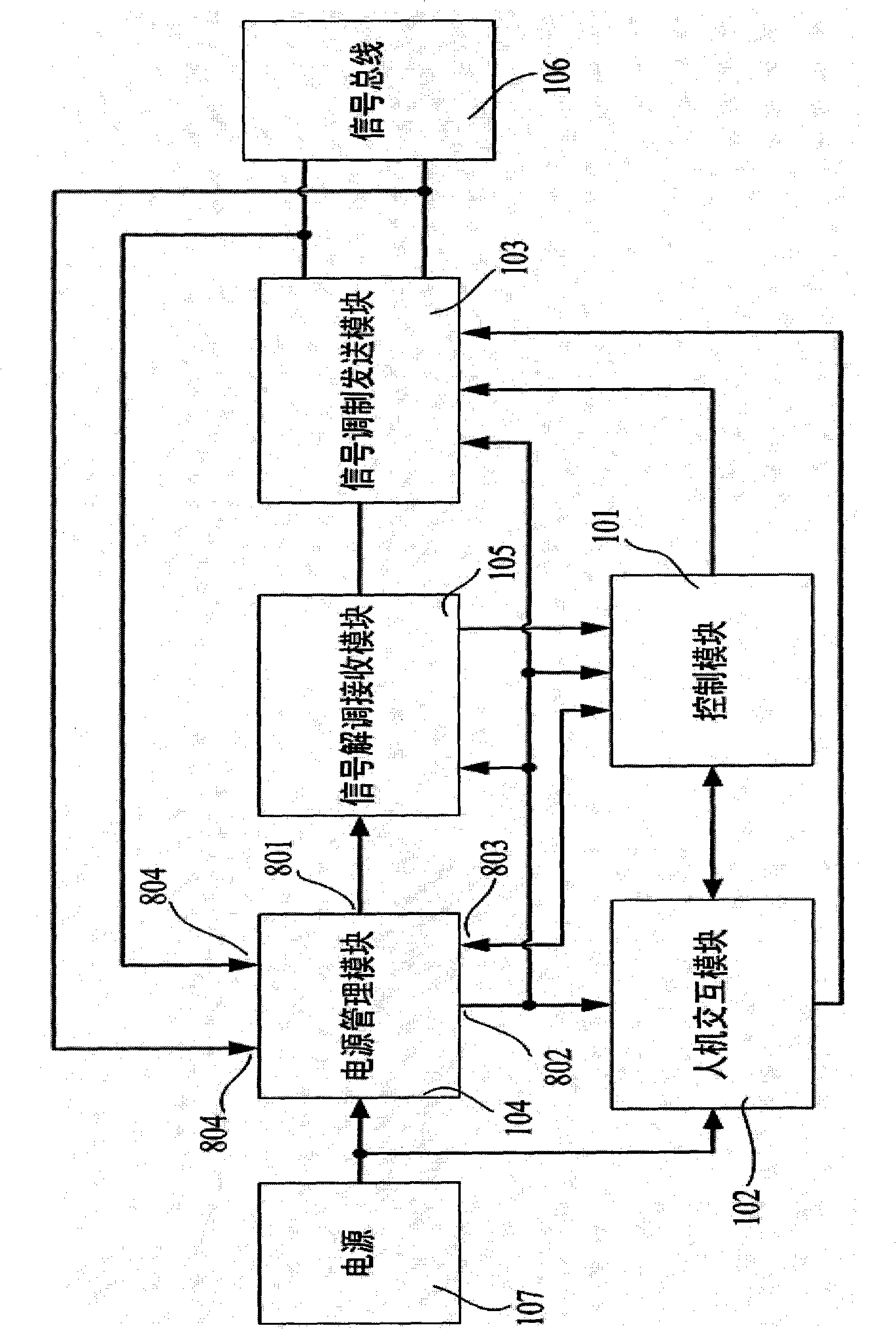
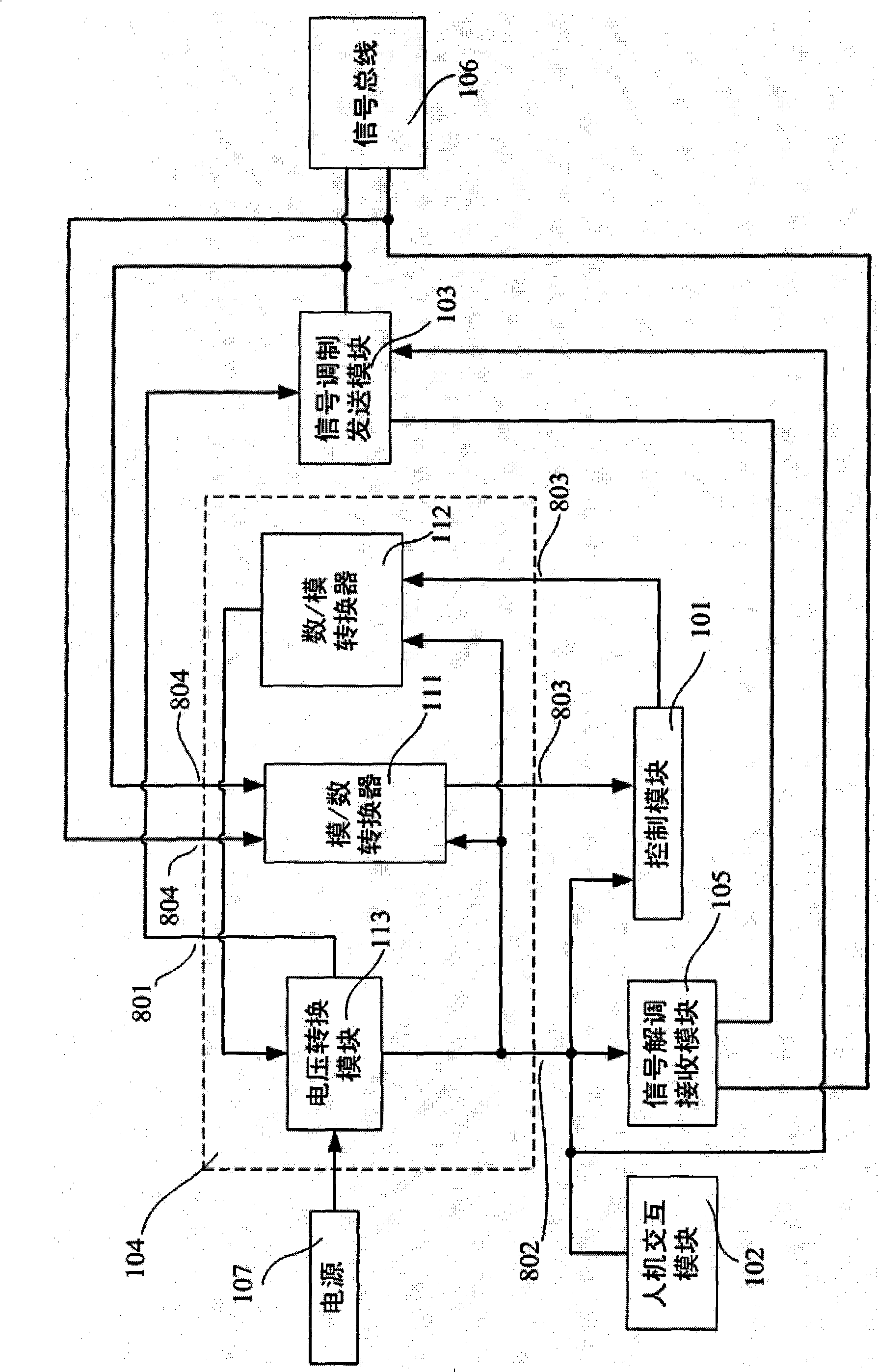
[0114] like Picture 1-1 and Figure 1-2 , an electronic detonator detonating device used in conjunction with the electronic detonator in the patent ZL03156912.9 and the patent application document 200820111269.7 or 200820111270.X, including a control module 101, a human-computer interaction module 102, a power management module 104, and a signal modulation and sending module 103 , a signal demodulation receiving module 105 , a signal bus 106 , and a power supply 107 . The detailed connection relationship is described as follows:

[0115] 1. The control module 101 is connected to the rest of the above modules except the power supply 107 and the signal bus 106, and communicates with the rest of the modules respectively. The control module 101 coordinates and controls the working status of these modules accor...


PUM


Abstract

The invention provides an electronic detonator initiation device, which comprises a control module, a man-machine interactive module, a power supply management module, a single modulation and transmission module, a signal demodulation and receiving module, a signal bus and a power supply, wherein the power supply management module can include an analog / digital converter, a digital / analog converter and a voltage conversion module; the signal modulation and transmission module can include a signal modulation module and a boost module; the signal demodulation and receiving module can include a signal sampling module and a signal conditioning circuit; and the man-machine interactive module can include a set and display device, and an authorization device, a locking device or an anti-misoperation switch. The invention also provides a main control process of the initiation device, and explains the flow processes of the communication voltage management process, the signal transmission process, the signal receiving process, the charging process and the initiation process in detail. According to the technical scheme, the initiation device matched with an electronic detonator can achieve the basic functions such as two-way communication with the electronic detonator and initiation of the electronic detonator.

Description

technical field [0001] The invention relates to the technical field of pyrotechnic detonation control, in particular to an initiating device which can be used in conjunction with an electronic detonator, can realize two-way communication with the electronic detonator, detonates the electronic detonator and other basic functions and its main control process. Background technique [0002] The existing electric detonator detonators generally use a series or series-parallel combination electric detonator network. When thousands of detonators are connected in series, in order to ensure that all the detonators in the network can detonate at the same time, the detonator detonator should be able to generate a current of one to several amperes instantaneously. There will be phenomena such as rejection of explosion and half explosion. The resistance of a single generator detonator is generally about one to several ohms, so the above-mentioned electric detonator detonator needs to hav...

Claims


Application Information

Patent Timeline
IPC IPC(8): F42D1/05
CPCF42D1/055
Inventor 颜景龙张宪玉刘星李风国赖华平
Owner 颜景龙
Learn More