System and method for operating a gas discharge lamp and method of use thereof

A technology of gas discharge lamps and square waves, applied to electric light sources, electrical components, lighting devices, etc., to achieve long life, reduce the number of parts, and reduce production and labor costs

Inactive Publication Date: 2008-12-10
KONINKLIJKE PHILIPS ELECTRONICS NV
View PDF2 Cites 2 Cited by
  • Summary
  • Abstract
  • Description
  • Claims
  • Application Information

AI Technical Summary

Problems solved by technology

[0003] The ballast of US 6232726, while functioning well for driving multiple lamps, requires a resonant circuit to ignite the lamps

Method used


Image

  • System and method for operating a gas discharge lamp and method of use thereof
  • System and method for operating a gas discharge lamp and method of use thereof
  • System and method for operating a gas discharge lamp and method of use thereof

Examples


Embodiment Construction

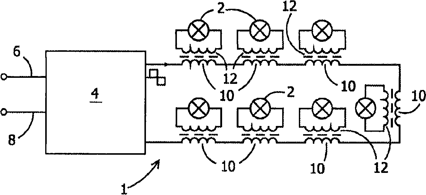
[0030] figure 1 A system 1 for operating at least one gas discharge lamp is represented. figure 1 This illustration shows seven gas discharge lamps 2 as an example. This system comprises a square wave current source 4 which can be connected to an external power source via wires 6,8. Preferably, the current source is connected to the mains grid. The primary windings 10 of a series of transformers are directly connected in series to the current source 4 . The secondary winding 12 of the transformer is connected to the corresponding gas discharge lamp 2 .

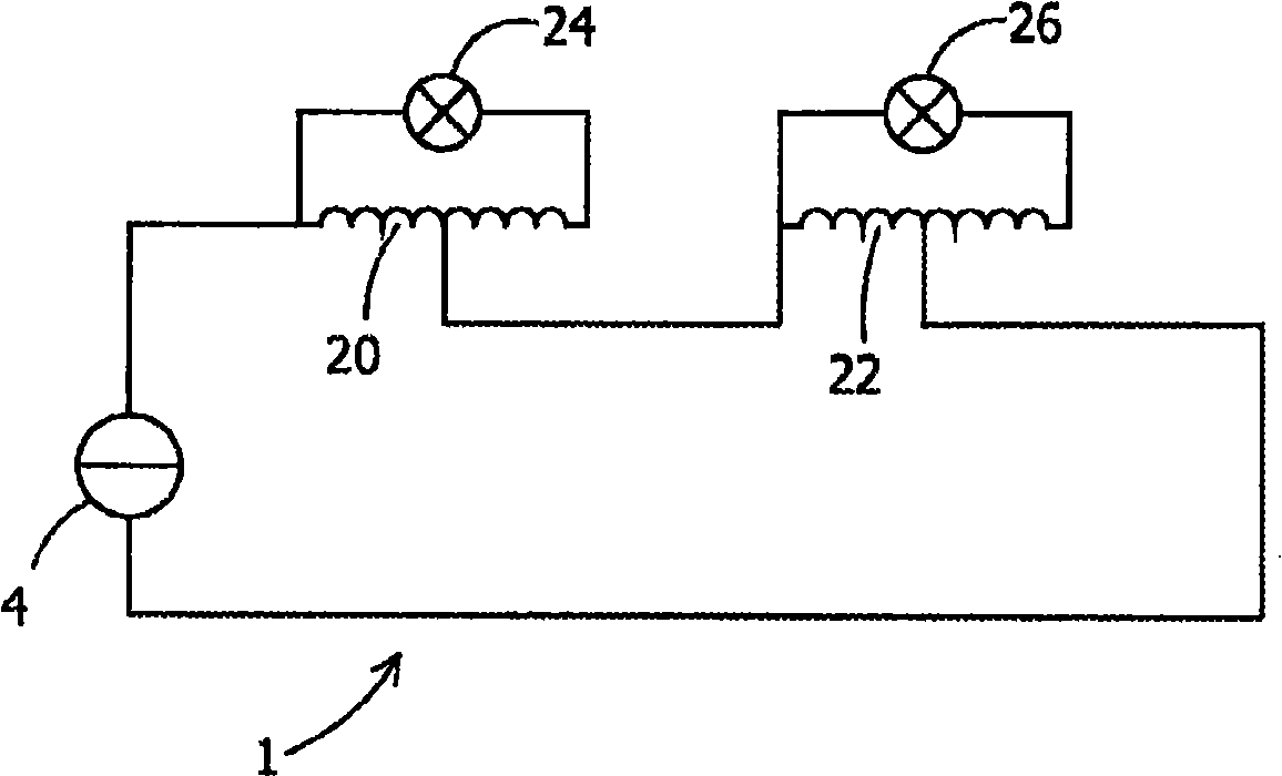
[0031] exist figure 2 In this modified embodiment of the present invention, the current source 4 is once again arranged to supply square-wave currents directly to, for example, the two transformers 20,22. But in this case the transformer is an autotransformer. The primary winding sections of these transformers are connected in series. The lamps 24, 26 are connected to the secondary winding portion of the transformer. ...


PUM


Abstract

The invention relates to a system for operating at least one gas discharge lamp comprising: a square wave current source for producing a substantially square wave current; and at least one transformer having a primary winding and at least one secondary winding; the at least one secondary winding being connectable to at least one gas discharge lamp; the square wave current source being directly coupled to the primary winding of the at least one transformer for directly providing the square wave current thereto.

Description

technical field [0001] The invention relates to a system and a method for operating at least one gas discharge lamp and to the use of said system. Background technique [0002] A conventional ballast system for powering a plurality of lamps, such as that disclosed in US6232726, includes an AC voltage source and a plurality of transformers for isolating said lamps from direct connection to said voltage source. The system includes a resonant circuit formed by the impedance of the resonant inductor and the primary winding of the transformer. The resonant capacitance of the resonant circuit required for lamp ignition is created by the capacitance of each transformer. Resonant inductance is formed by resonant inductors. The secondary winding of each transformer is connected to said lamp. [0003] The ballast of US 6232726, while functioning well for driving multiple lamps, requires a resonant circuit to ignite the lamps. Also, connecting and disconnecting a lamp will affect t...

Claims


Application Information

Patent Timeline
IPC IPC(8): H05B41/288
CPCH05B41/2881
Inventor B·辛佩拉尔
Owner KONINKLIJKE PHILIPS ELECTRONICS NV
Why Eureka
Try Eureka