Wind power plant with lightning protection arrangement

A technology for wind energy equipment and lightning protection, which is applied in wind energy generation, mechanical equipment, cable installation, etc., and can solve problems such as high cost and time-consuming

Inactive Publication Date: 2008-12-10
LM GLASSFIBER
View PDF1 Cites 0 Cited by
  • Summary
  • Abstract
  • Description
  • Claims
  • Application Information

AI Technical Summary

Problems solved by technology

Due to the damage caused by flashover the blades have to be repaired or in the worst case replaced, since performing repairs or replacing blades is very complicated, especially for offshore wind energy installations, it is a time-consuming and cost-intensive process. cost process
[0004] Also, since carbon fibers are also typically conductive, it is problematic to provide lightning receptors as well as lightning protection within blades made of carbon fibers

Method used


Image

  • Wind power plant with lightning protection arrangement
  • Wind power plant with lightning protection arrangement
  • Wind power plant with lightning protection arrangement

Examples


Embodiment Construction

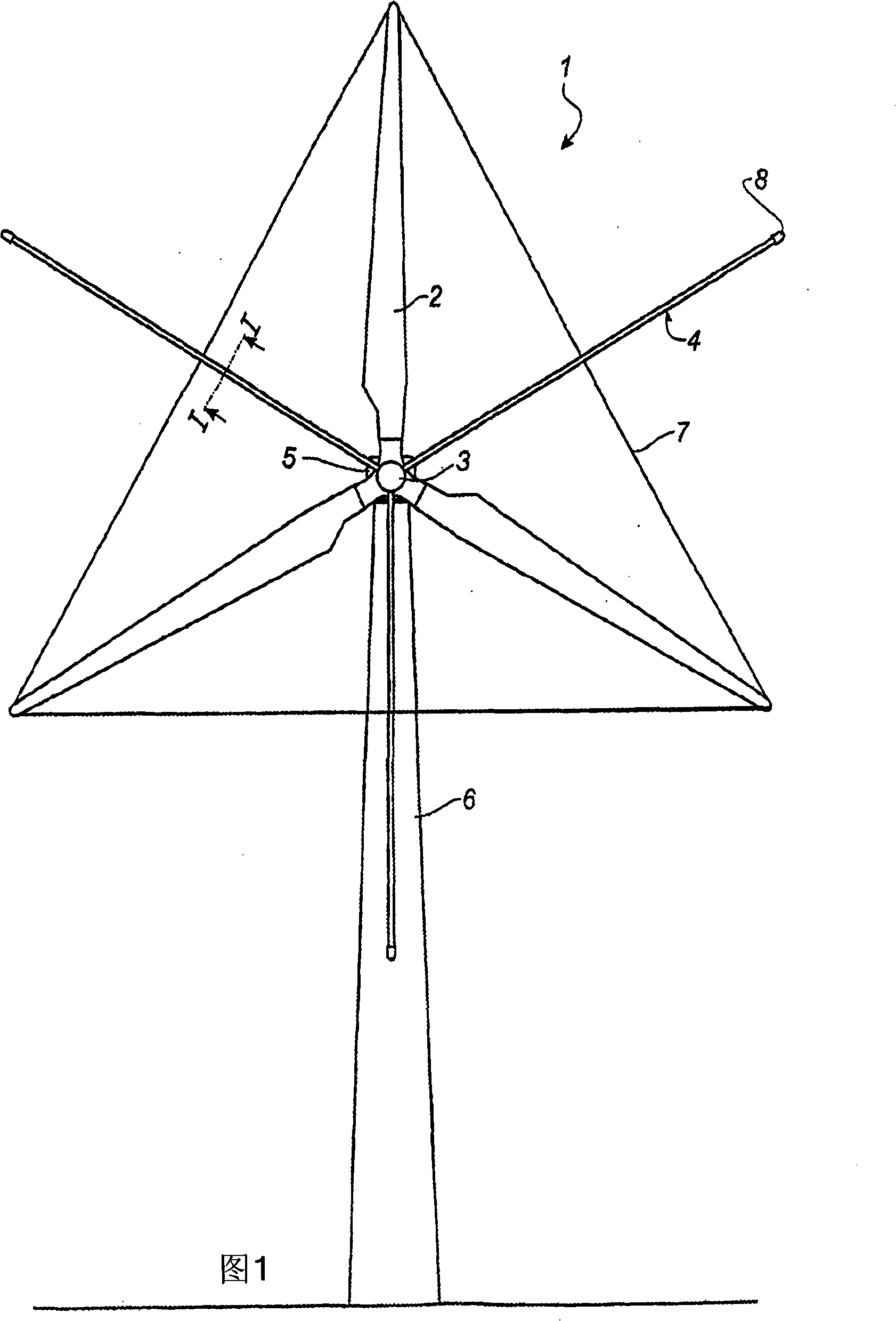
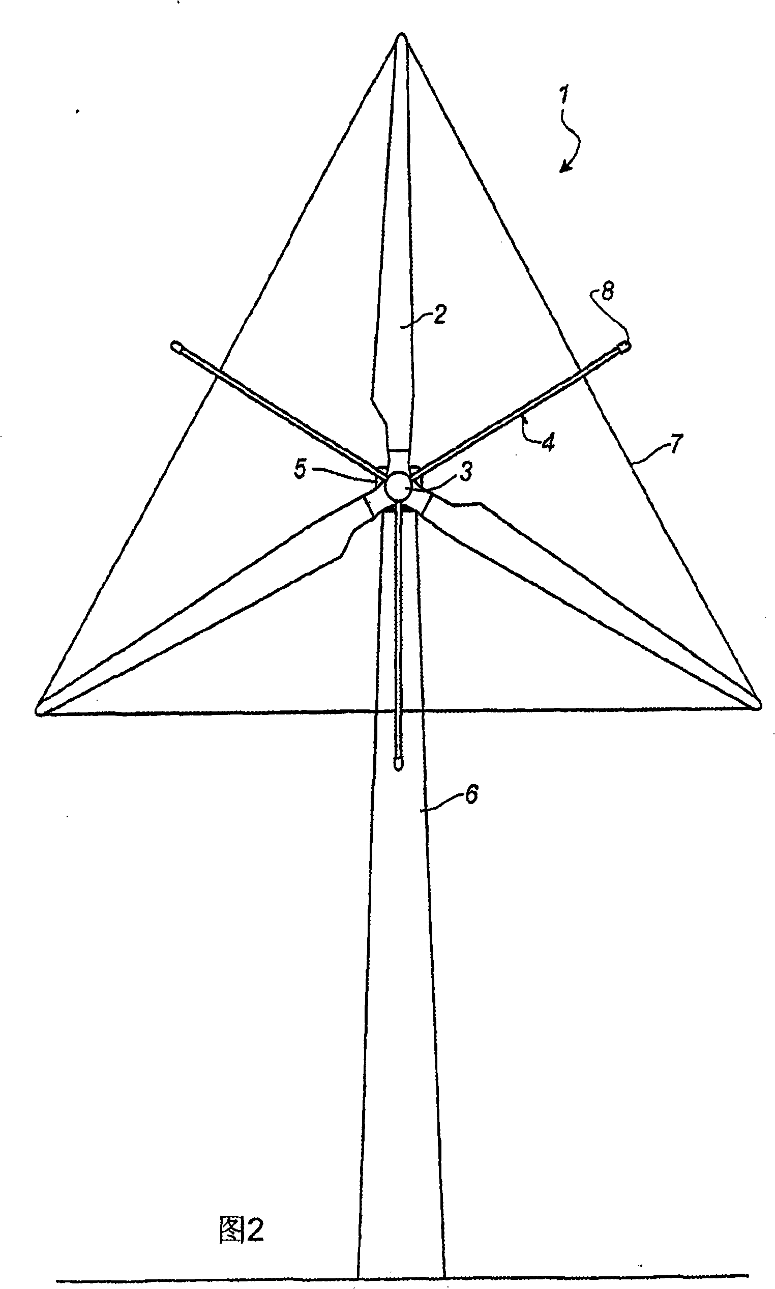
[0026] The wind power plant shown in FIG. 1 comprises a tower 6 supporting a nacelle 5 (also called windmill shell). A substantially horizontal main shaft projects outwardly from the nacelle 5 . A rotor is mounted on the shaft, and the rotor includes a hub 3 and a plurality of blades 2 . The rotor can be rotated by the wind. Preferably, the wind energy plant 1 is a so-called upwind plant, in which the wind hits the rotor before hitting the tower 6 , and in which the nacelle 5 can swing, that is to say rotate about a vertical axis relative to the tower 6 . The rotor thus adjusts itself to the direction of the wind at any given moment. Also, as shown in FIG. 2, the wind energy plant is preferably provided with three blades 2, which extend substantially radially outwards from the hub 3 and form a so-called shell made of polymeric material supplemented with glass fibers or carbon fibers production.

[0027] A typical feature of the wind energy plant 1 shown in FIG. 1 is that i...


PUM


Abstract

A wind power plant (1) having a lightning protection arrangement comprises a plurality of blades (2) extending radially outwards from a hub (3) and together with said hub forming the rotor. An electrically conductive lightning protection means (4) is arranged between two adjacent blades (2).

Description

【Technical field】 [0001] The invention relates to a wind energy device with a lightning protection device, wherein the wind energy device includes a plurality of blades extending radially outward from a hub, and forms a rotor together with the hub. 【Background technique】 [0002] It is known to provide lightning protection systems for blades to protect them from lightning strikes. As an example, WO96 / 07825 discloses a lightning protection system in which so-called lightning receptors with electrically conductive material are provided to the blade tip. This lightning receptor is able to "catch" a lightning strike and conduct the current through a downstream lightning protection device extending longitudinally of the blade and grounded through the hub. The system has been proven to provide specific and effective protection. [0003] However, since water is conductive, there is a risk of flashover or spark discharge from the lightning receiver or lightning protection to the s...

Claims


Application Information

Patent Timeline
Patent Type & Authority Applications(China)
IPC IPC(8): F03D11/00H02G13/00
CPCH02G13/00H02G13/80F03D80/30Y02E10/72
Inventor P·格拉保
Owner LM GLASSFIBER
Why Eureka
Try Eureka