Electromagnetic driven breaker

A technology of electromagnetic drive and circuit breaker, which is applied to the power device inside the switch, etc., can solve the problems of difficult production and manufacturing, complex structure, and high requirements for parts technology.

Active Publication Date: 2008-12-10
JIANGSU DAQO KFINE ELECTRIC
View PDF1 Cites 0 Cited by
  • Summary
  • Abstract
  • Description
  • Claims
  • Application Information

AI Technical Summary

Problems solved by technology

The structure of the above-mentioned existing mechanism is complicated, the number of parts usually exceeds 100, and the requirements for the parts technology are high, so it is difficult to manufacture

Method used


Image

  • Electromagnetic driven breaker
  • Electromagnetic driven breaker
  • Electromagnetic driven breaker

Examples


Embodiment 1

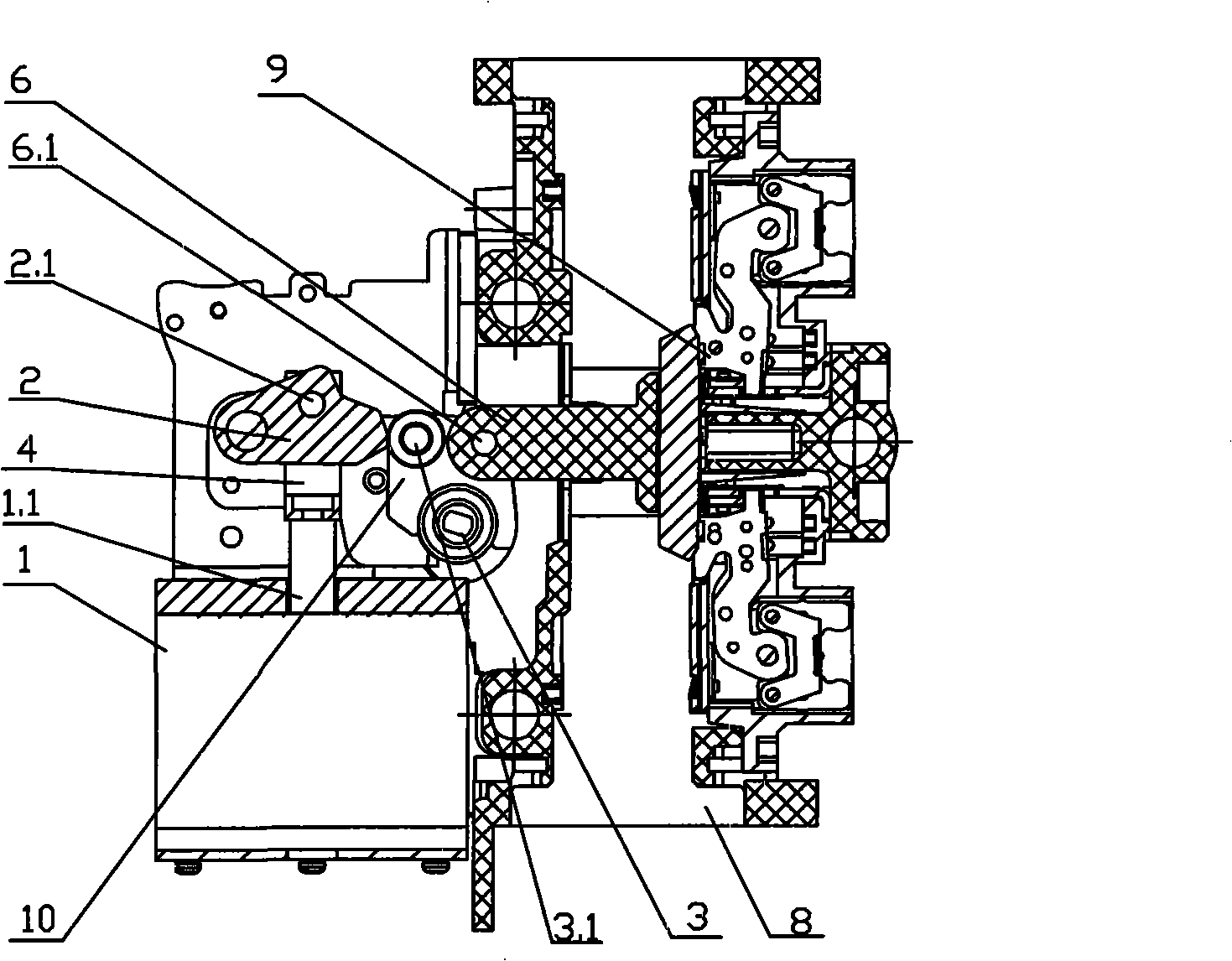
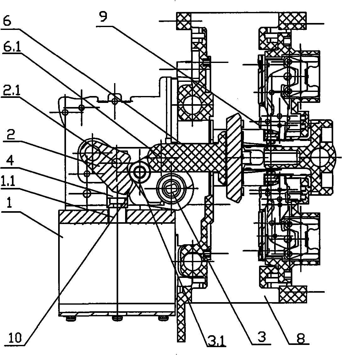
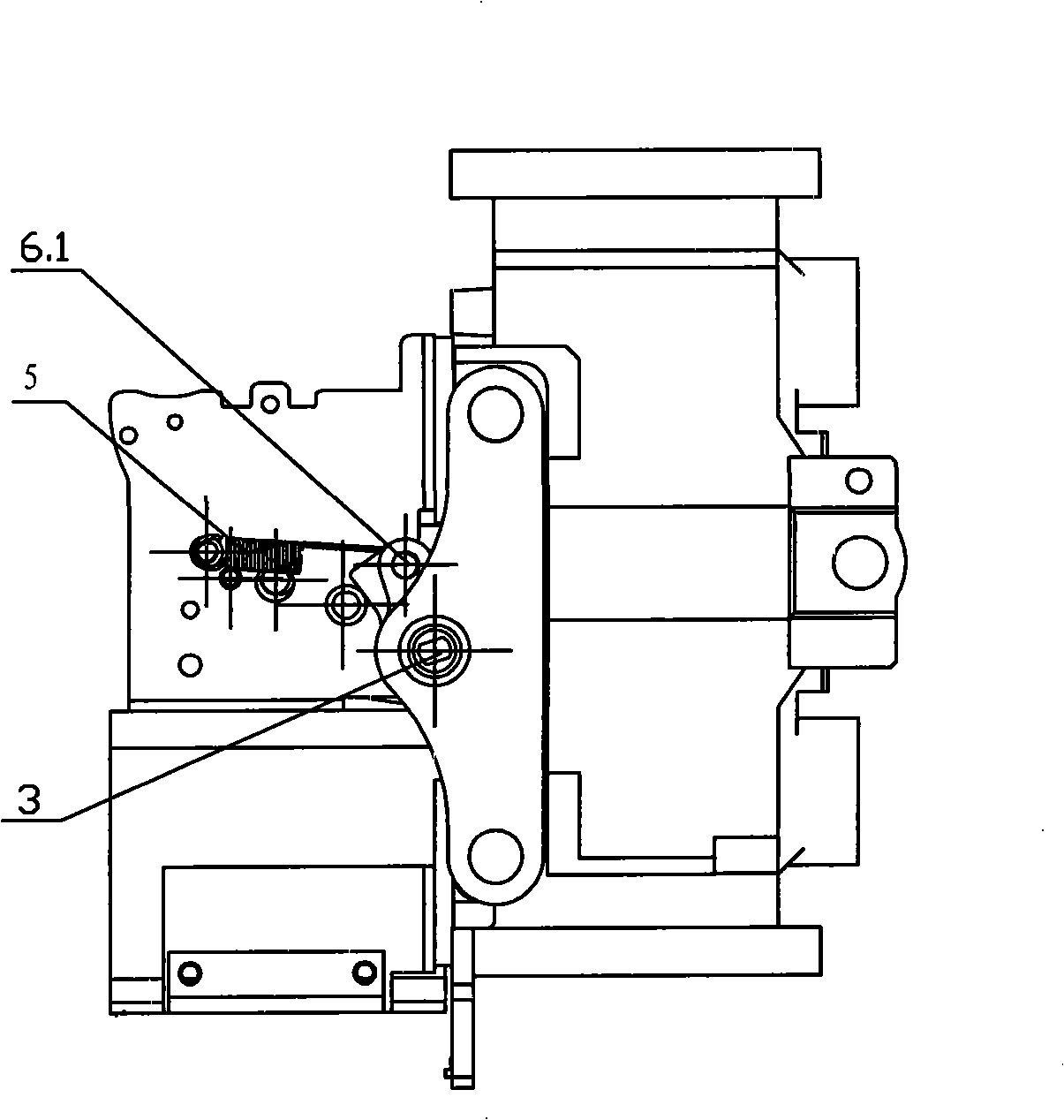
[0011] In this example, if Figures 1 to 3 As shown, a pair of static contacts 9 are fixed in the housing 8, and the relative position of the static contacts 9 is equipped with a moving contact 6, and the end of the moving contact away from the static contact 9 is connected to the drive shaft rotating plate 10 through the hinge pin 6.1 Hinged, the hinge pin 6.1 is hung with a return spring 5 (see image 3 ). The drive shaft rotating plate 10 is fixedly connected with the drive shaft 3 and supported on the casing 8 through the drive shaft 10 . One side of the housing is equipped with a permanent magnet drive device 1 . The permanent magnet driving device contains a moving iron core 1.1 that can be driven by electromagnetic force, and has two extreme positions of extension and retraction, and its outer end passes through the connecting rod 4 and the cam 2 installed in the housing 8 through the pin 2.1 are hinged to form a crank linkage mechanism, wherein the moving iron core ...


PUM


Abstract

The invention provides a solenoid drive circuit breaker, relating to circuit switch control device technical field. A fixed contact is fixed in housing of the circuit breaker, a moving contact is mounted at relative position of the fixed contact. The moving contact is joined with a drive rotation shaft by a movement pair. One side of the housing is mounted with a solenoid drive device containing a moving core. The moving core is provided with a first and a second position, of which one end is hinged with a cam hinged in the housing by a connection rod to form a crank connection rod mechanism. One end of the moving contact far from the fixed contact is hinged with a rotation board of the drive shaft which is fixedly connected with the drive shaft and supported on the housing by the drive shaft. One side of rotation board of the drive shaft is mounted with a roller which forms a cam pair together with outline of the cam. When the moving core is respectively in the first and the second positions, outline of the cam is respectively corresponding to on and off positions of the moving contact. The invention is capable of implementing contact on and off function, which is the same as original circuit breaker, with structure greatly simplified, technical demand obviously reduced so as to effectively decrease production cost.

Description

technical field [0001] The invention relates to a circuit breaker, in particular to an electromagnetically driven circuit breaker, and belongs to the technical field of circuit on-off control devices. Background technique [0002] A circuit breaker is a commonly used circuit on-off control device. The casing of the existing circuit breaker is equipped with a static contact and a moving contact opposite to the static contact, the static contact is fixed in the casing, and the moving contact is connected with the driving shaft through a kinematic pair. As far as the applicant knows, the existing typical moving contacts of circuit breakers need to be driven and controlled by a spring operating mechanism, which usually uses a spring to store energy, and then drives the rotating shaft to rotate through the principle of complex four-link movement into five-link, so that Realize the opening and closing of the contacts of the circuit breaker (refer to the Chinese patent application...

Claims


Application Information

Patent Timeline
Patent Type & Authority Applications(China)
IPC IPC(8): H01H3/28
Inventor 陈晓菊王立强房淑华
Owner JIANGSU DAQO KFINE ELECTRIC
Why Eureka
Try Eureka