
Coupling method of shunting disk for thermal state furnace slag process

A diverter plate and slag technology, which is applied in the field of diverter plates for hot slag treatment, can solve the problems that the diverter plate cannot be positioned and connected, affects the service life of the diverter plate, and the workload of connection and disassembly is large, so as to prevent the inability to locate and connect , good force transmission function, and the effect of reducing maintenance workload

Active Publication Date: 2008-12-03
BAOSHAN IRON & STEEL CO LTD
View PDF1 Cites 0 Cited by
  • Summary
  • Abstract
  • Description
  • Claims
  • Application Information

AI Technical Summary

Problems solved by technology

The outer surface of the "A"-shaped panel is the working surface and has screw holes. The fan-shaped panels are respectively connected to the two panels of the support device through bolts, and the workload of connection and disassembly is large; and the slag flow needs to flow through the " Only the outer side of the A”-shaped panel can enter the cavity. During operation, the fan-shaped panel is constantly rubbed against the medium in the cavity. When the panel wears a lot, the bolt head will be worn off, and the fan-shaped surface will be opened by heat, and the connection will also be broken. The bolts were broken, which caused the distribution plate to be unable to be positioned and connected; after long-term use, the “A”-shaped sectors of the distribution plate will have unequal thermal expansion due to uneven heating, resulting in a large gap between the “A”-shaped sectors. If the slag flows into the distribution plate through the gap, it will affect the service life of the distribution plate
In addition, when replacing the diverter plate, the bolts must be blown off with an oxygen gun first, resulting in long maintenance time and affecting normal operation

Method used


Image

  • Coupling method of shunting disk for thermal state furnace slag process
  • Coupling method of shunting disk for thermal state furnace slag process
  • Coupling method of shunting disk for thermal state furnace slag process

Examples


Embodiment

[0027] see Figure 7 , put the key 4 into the shaft 5, and then assemble the key 4 and the shaft 5 into the sleeve 33 of the diverter plate device 8 of the present invention, so that the key 4 and the keyway 35 are closely matched.

[0028] During operation, the external transmission mechanism drives the shaft 5 to rotate around its axis, and due to the transmission of the key 4, the diverter plate device 8 and the shaft 5 rotate together. Metallurgical slag 6 falls from the slag tank 7 onto the rotating splitter plate 8, touches the outer surface of its working plate 11, and flows outward along the outer surface of the working plate 11 by gravity and leaves the splitter plate device 8 .

[0029] Since the splitter tray device 8 is continuously impacted by the molten slag 6, the outer surface of the splitter tray device 8 has a heavy workload and poor environment. However, through the internal connection method of the present invention, each component is connected on the int...


PUM


Abstract

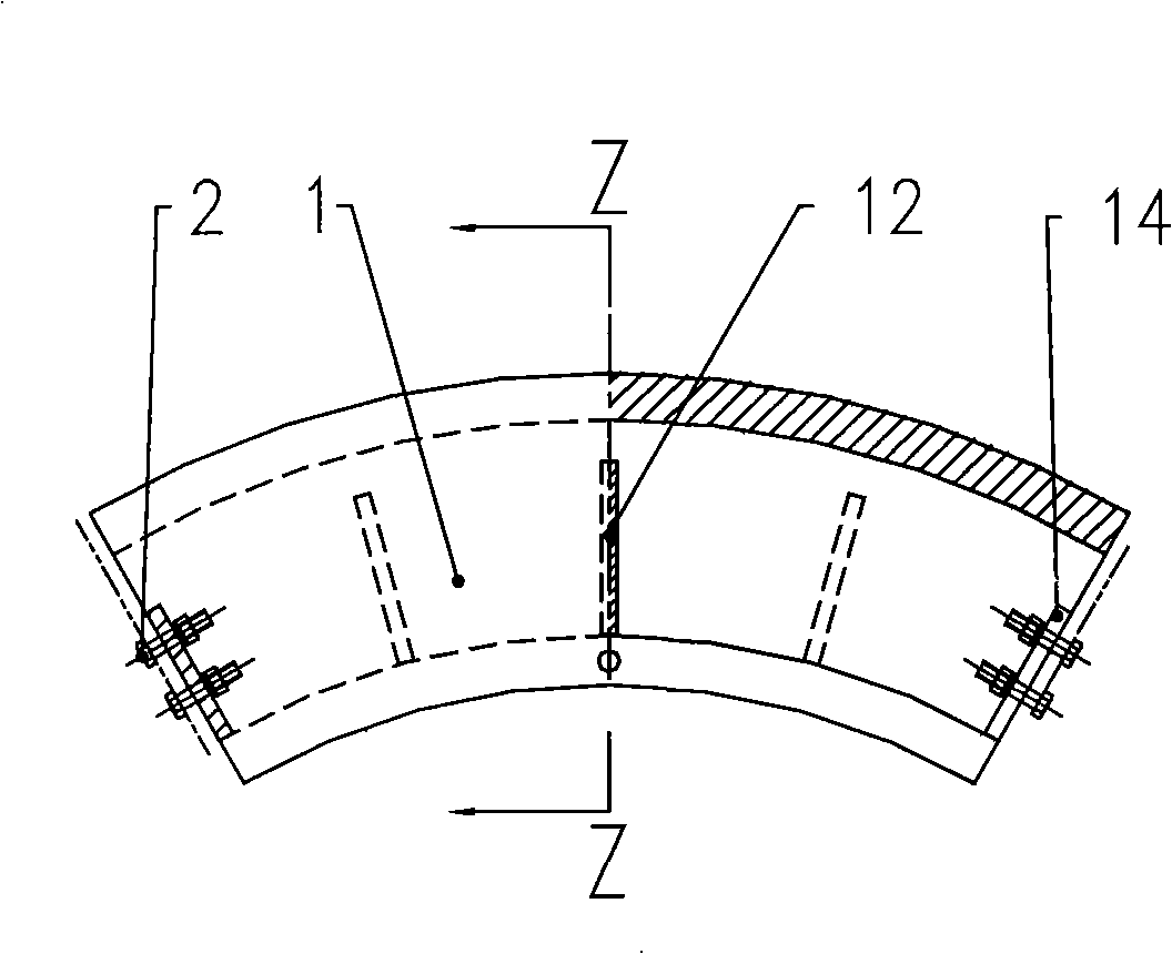
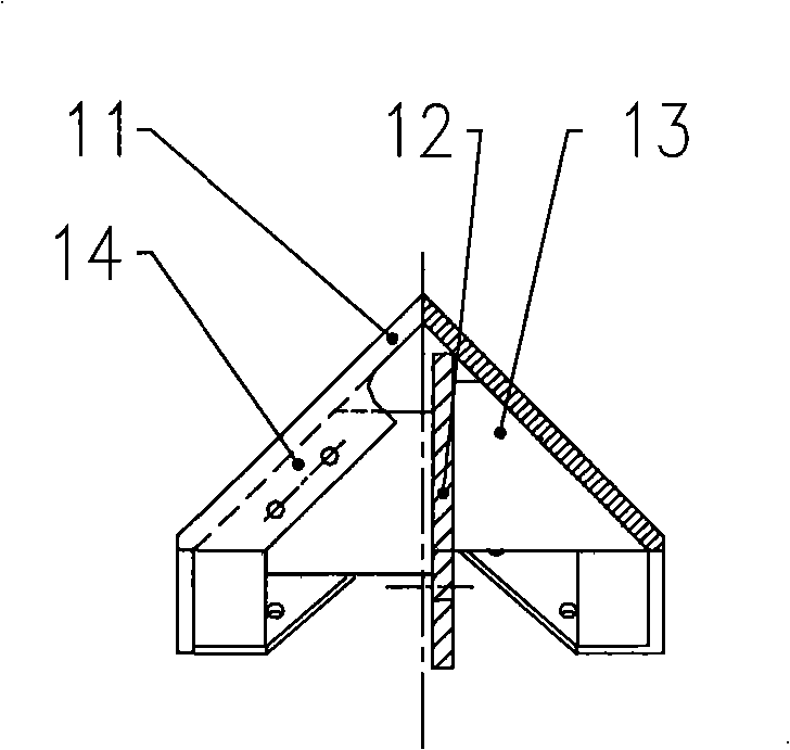
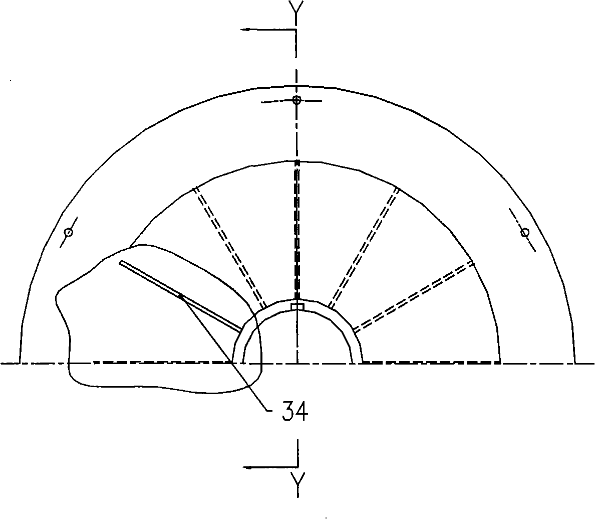
The invention relates to a flow-split disk used for disposing the hot-state furnace slag and a method for joining the flow-split disk used for disposing the hot-state furnace slag. The flow-split disk consists of a frustum member and a cone-shaped support which are joined together by adopting internal assembly method. The frustum member consists of a plurality of segments shaped like the Chinese character 'ge'. Each segment consists of three fan-shaped ring plates which are arranged to form the shape of the Chinese character 'ge' and fixedly and mutually connected with rib plates. Connecting plates with threaded holes are arranged on two end surfaces of each segment. The segments are connected as a whole via bolts. The cone-shaped support has a frame structure shaped like the Chinese character 'sa' and is formed by fixedly connecting an intermediate ring plate, lateral ring plates on two sides, a shaft sleeve perpendicular to the support and a rib plate, wherein the diameter of the intermediate ring plate is slightly larger than that of the lateral ring plate. The intermediate ring plate of the cone-shaped support and the middle plates of the segments of the frustum member are fixedly connected via bolts, so as to form the flow-split disk. A lateral panel is covered on the lateral ring plates. The flow-split disk prolongs the service life and improves the safety of the flow-split disk.

Description

technical field [0001] The invention relates to a diverter tray for hot slag treatment. Background technique [0002] Compared with other metallurgical slag treatment technologies, the double-chamber roller metallurgical slag treatment technology has the advantages of short process, less investment, safety and reliability, low energy consumption, direct utilization of treated slag, and less pollution, and has been gradually recognized and recognized by the industry. Promote quickly. The diverter plate in the double-chamber drum metallurgical slag treatment device is to make the slag fall onto the rotating diverter plate and be divided into two paths to enter the cylinder for treatment. Because it works in a high temperature environment of about 1000 ° C, the diverter plate is easy to deform , need to be replaced and repaired frequently. Chinese patent 03255576.8 discloses a "combined diverter plate for hot slag treatment". The combined diverter plate is composed of a surfa...

Claims


Application Information

Patent Timeline
Patent Type & Authority Applications(China)
IPC IPC(8): F23J1/06C21B3/06
CPCY02W30/50
Inventor 肖永力崔健刘茵李永谦
Owner BAOSHAN IRON & STEEL CO LTD
Learn More