
Satellite digital video broadcast receiving circuit and signal receiving method thereof

A digital video broadcasting and receiving circuit technology, which is applied in the field of satellite digital video broadcasting, can solve the problem of high cost of DVB-S system installation

Inactive Publication Date: 2008-11-26
MSTAR SEMICON INC
View PDF0 Cites 4 Cited by
  • Summary
  • Abstract
  • Description
  • Claims
  • Application Information

AI Technical Summary

Problems solved by technology

In other words, the satellite signals received by each LNB need to be processed by a separate DVB-S receiver, resulting in a high cost of setting up the DVB-S system

Method used


Image

  • Satellite digital video broadcast receiving circuit and signal receiving method thereof
  • Satellite digital video broadcast receiving circuit and signal receiving method thereof
  • Satellite digital video broadcast receiving circuit and signal receiving method thereof

Examples


Embodiment Construction

[0018] The above and other technical features and advantages of the present invention will be described in more detail below in conjunction with the accompanying drawings.

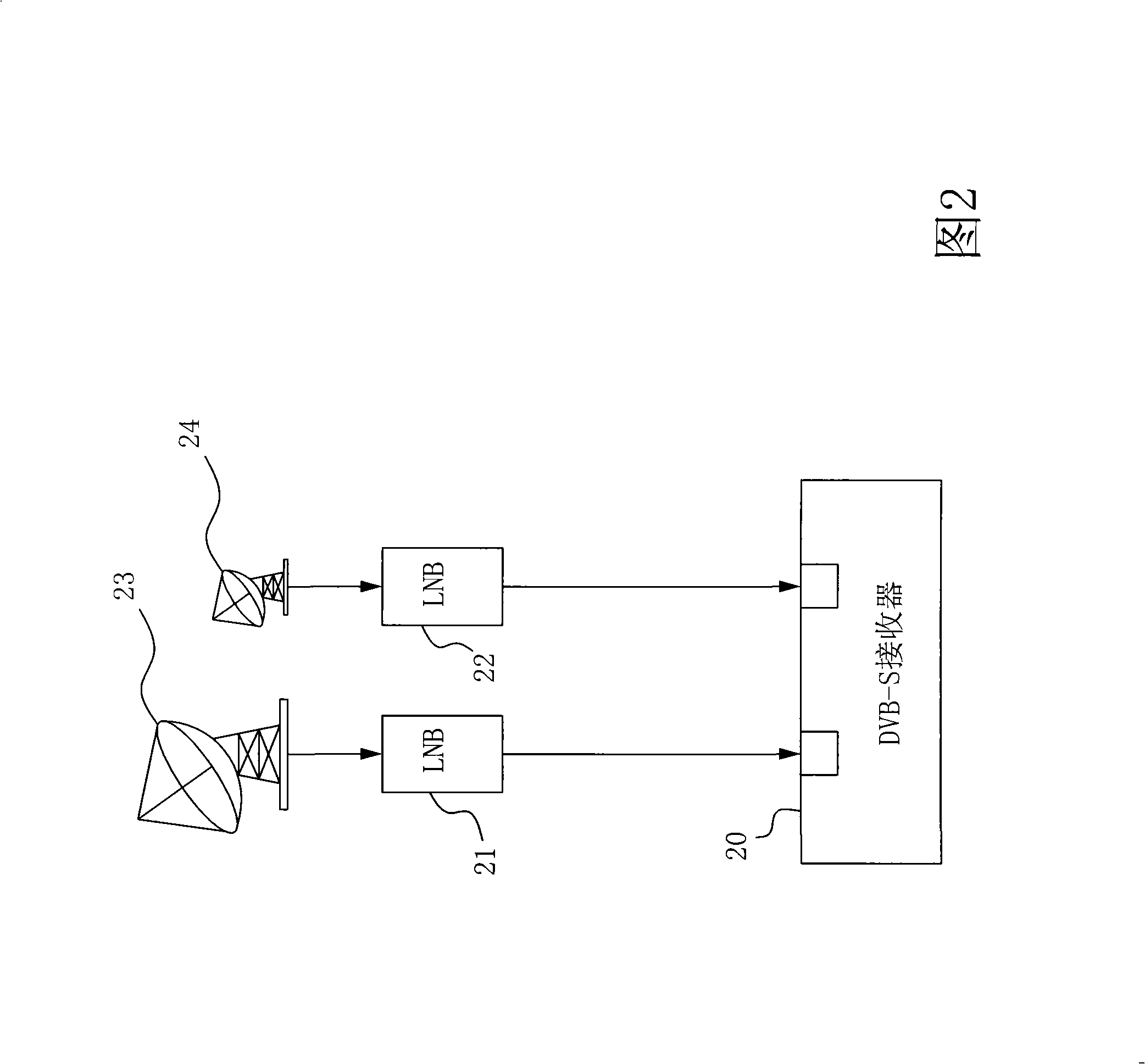
[0019] Fig. 2 is the frame diagram of the DVB-S system according to an embodiment of the present invention, and low-noise downconverter (LNB) 21,22 receives the signal of different satellites respectively from antenna 23,24, through down-frequency processing, outputs respectively the first A satellite input signal and a second satellite input signal. The DVB-S receiver 20 has two input terminals, which can respectively receive the first and second satellite input signals from the LNBs 21 and 22, so that a single DVB-S receiver can receive the satellite signals from the two LNBs.

[0020] FIG. 3 is a block diagram of a DVB-S receiving circuit 30 in a preferred embodiment of the present invention, wherein the DVB-S receiving circuit 30 and the DVB-S tuner 34 are located in the DVB-S receiver 20 of FIG. 2 , a...


PUM


Abstract

The invention relates to a digital video broadcasting (DVB-S) receiving circuit with multiple inputs and a signal receiving method, which can receive the planet input signals provided by a plurality of low noise frequency alias demultiplier (LNB), to reduce the construction cost of the DVB-S system. The DVB-S receiving circuit comprises a selecting circuit and a bonding device, wherein the selecting circuit comprises a plurality of signal paths for receiving and transmitting a plurality of planet input signals, the selecting circuit triggers one of the signal paths according to a control signal to output one of the planet input signals, the bonding device bonds the signal paths into a single path to be connected with a DVB-S turner for following treatment.

Description

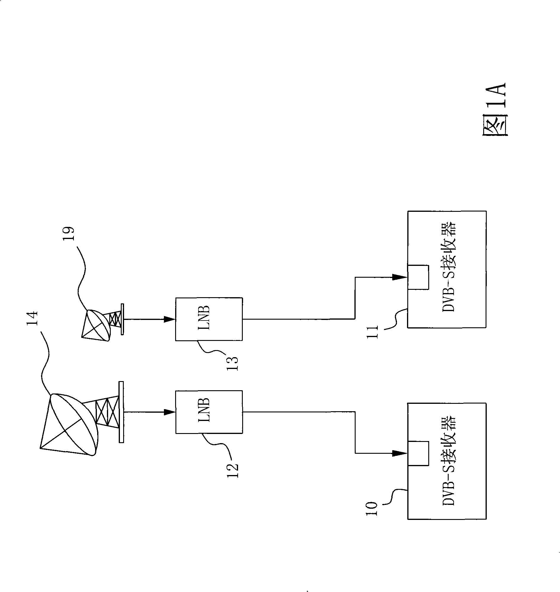
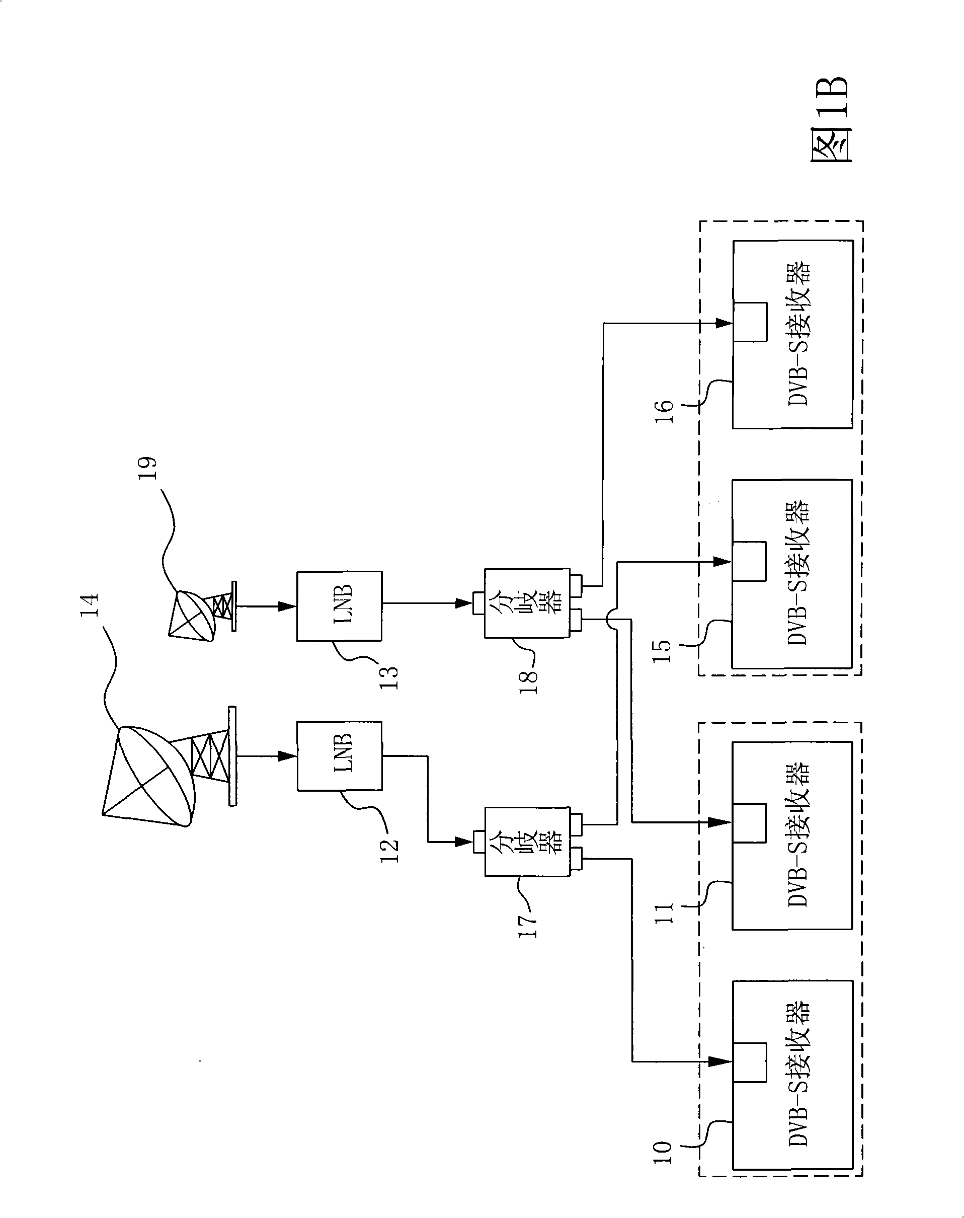
technical field [0001] The invention relates to a Digital Video Broadcasting-Satellite (DVB-S for short), especially a DVB-S receiving circuit with multiple input terminals and a signal receiving method thereof. Background technique [0002] Satellite digital video broadcasting is a widely used digital satellite TV transmission specification. For each satellite channel signal (usually a video of a different channel), it is first down-converted by a low noise block (LNB) , and then sent to individual DVB-S receivers for subsequent processing. FIG. 1A is a structure diagram of a DVB-S system in the background technology, which receives signals from two different satellites through antennas 14, 19 and LNBs 12, 13, and sends them to DVB-S receivers 10, 11 respectively. In other words, the satellite signals received by each LNB need to be processed by a separate DVB-S receiver, which results in a high cost of setting up the DVB-S system. [0003] For example, when setting up a ...

Claims


Application Information

Patent Timeline
Patent Type & Authority Applications(China)
IPC IPC(8): H04N5/44H04N5/50H04N7/20
Inventor 陈寿芳
Owner MSTAR SEMICON INC
Learn More