
Barrier sealing system for centrifugal compressors

一种压缩机、压缩机转子的技术,应用在发动机的密封、用于弹性流体的泵送装置的部件、液体变容式机械等方向,能够解决不能有效地防止油运移等问题

Inactive Publication Date: 2008-11-26
GENERAL ELECTRIC CO
View PDF0 Cites 8 Cited by
  • Summary
  • Abstract
  • Description
  • Claims
  • Application Information

AI Technical Summary

Problems solved by technology

[0003] However, barrier body seals are not effective in preventing oil migration at reduced buffer airflow
For example, a barrier body seal is not effective in preventing oil migration from the bearing to the dry gas seal if the flow under the seal is relatively small compared to the effective clearance of the seal

Method used


Image

  • Barrier sealing system for centrifugal compressors
  • Barrier sealing system for centrifugal compressors
  • Barrier sealing system for centrifugal compressors

Examples


Embodiment Construction

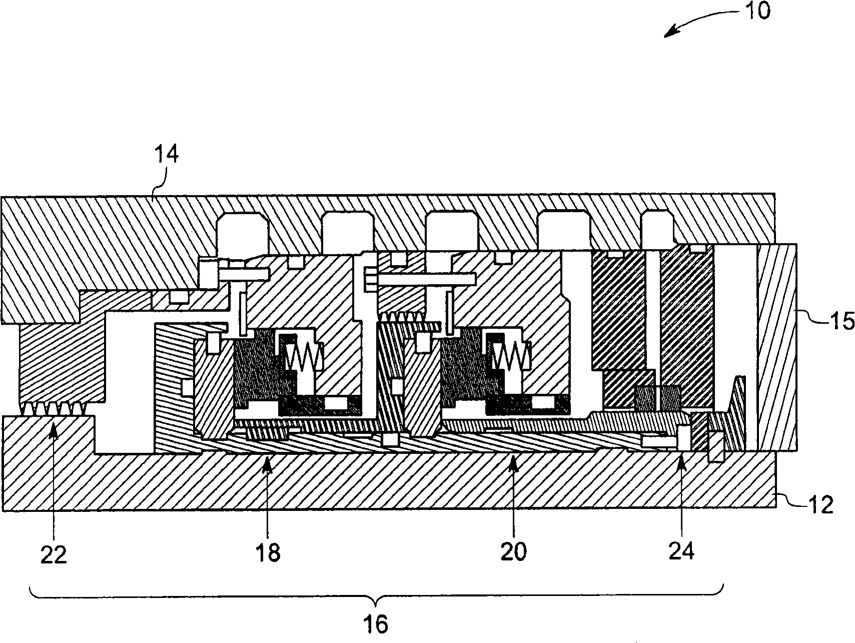
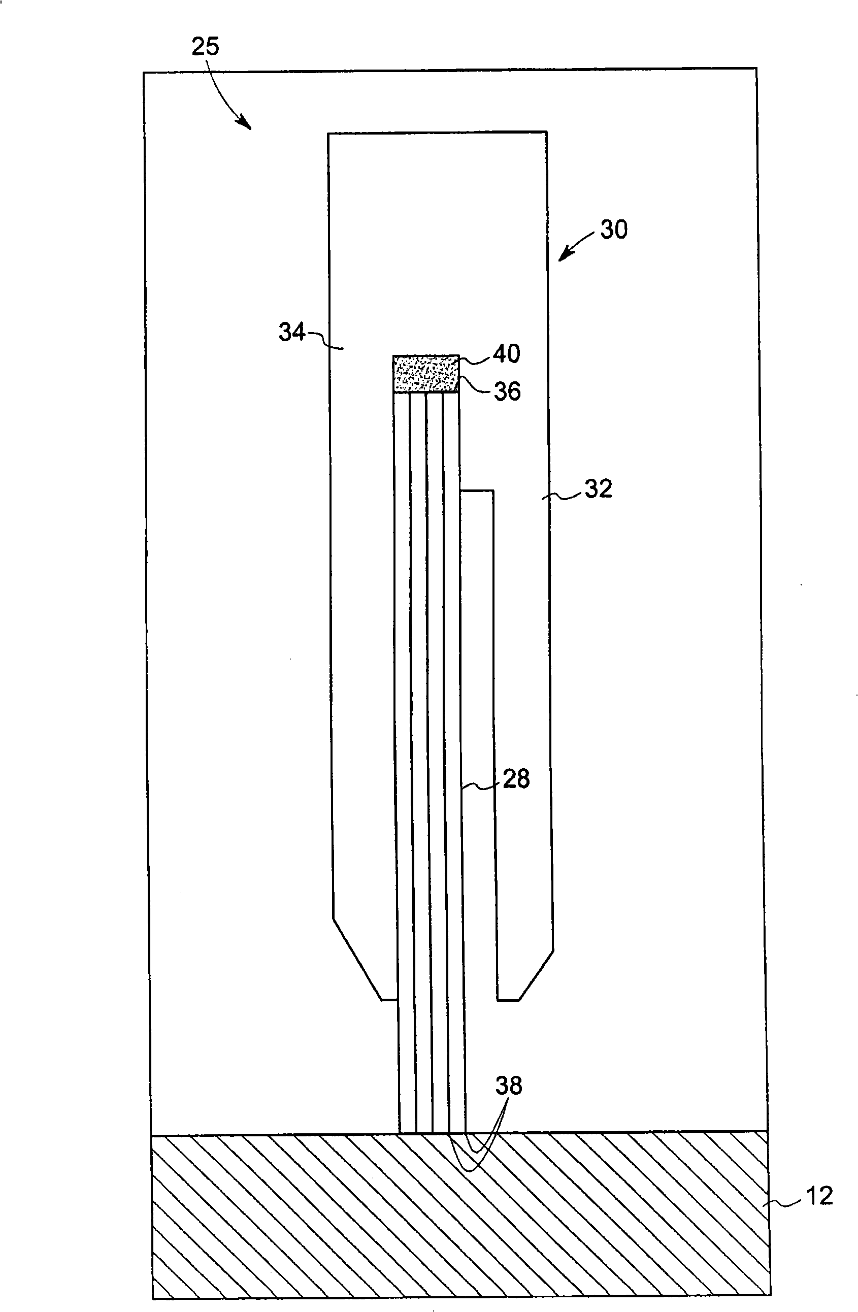
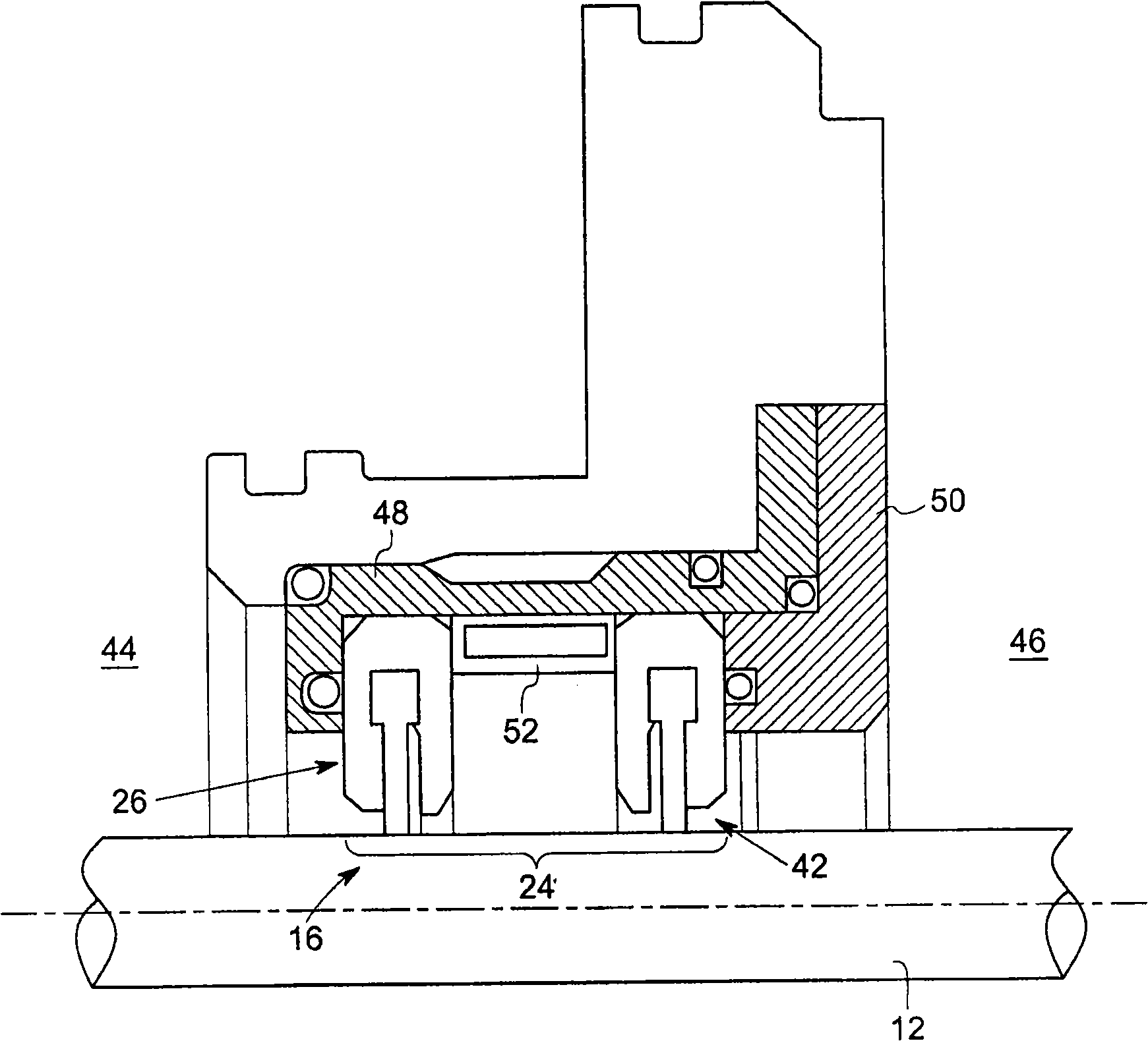
[0050] As discussed in detail hereinafter, embodiments of the present invention provide a rotating machine with a sealing arrangement disposed between a machine rotor and a machine stator. The sealing arrangement includes a dry gas seal, a first seal disposed on a first side between the dry gas seal and the bearing and a first seal disposed on a second side between the first seal and the bearing to provide a rotor of the machine. Two seals. In some exemplary embodiments, the first seal comprises a brush seal comprising non-metallic fibers. In some exemplary embodiments, the second seal includes a brush seal. In some exemplary embodiments, the first seal and the second seal may include brush seals each including a plurality of non-metallic fibers. Both the first seal and the second seal are configured to prevent oil leakage towards the dry gas seal. In some embodiments, other seals such as labyrinth seals or carbon face seals are used in conjunction with the first and second...


PUM


Abstract

The invention discloses a barrier sealing system for centrifugal compressors; wherein, a rotary machine (10) includes a machine rotor (12), a bearing (15) coupled to the machine rotor (12), a machine stator (14), and a sealing device (16) disposed between the machine rotor (12) and the machine stator (14). The sealing device (16) includes a dry gas seal (18, 20) and first and second seals (26, 42) disposed between the dry gas seal (18, 20) and the bearing (15). One or both of the first and second seals (26, 42) includes a brush seal or more specifically a brush seal including a plurality of non-metallic fibers (28).

Description

technical field [0001] The disclosed embodiments relate generally to rotating machines, and more particularly to sealing systems for interfaces between rotating and stationary components. Background technique [0002] Rotary machines, such as centrifugal compressors, often use dry gas seals in order to limit leakage of process gas to the atmosphere along the rotatable shaft. Lubricating oil supplied to one or more radial bearings of a rotatable shaft often tends to wick away along the rotor shaft and contaminate the tip surface of the dry gas seal. A barrier seal (also referred to as a "tertiary seal") is provided between the dry gas seal and the radial bearing in order to prevent oil migration towards the dry gas seal. Typically, a barrier seal includes a pair of seals with a gas flow path between the pair of seals. Barrier seals may include labyrinth seals, carbon face seals, metallic brush seals, and the like. [0003] However, barrier body seals are not effective in p...

Claims


Application Information

Patent Timeline
Patent Type & Authority Applications(China)
IPC IPC(8): F04D29/08F04D29/02F04D17/10
CPCF16J15/3288F16J15/006F01D11/001F04D29/102F01D11/04F01D25/16F05D2240/56F04D17/10F04D29/023F04D29/083F05D2250/15F05D2250/25F04B39/00
Inventor R·M·卢斯特德C·E·沃尔夫E·J·鲁吉罗G·马里奥蒂
Owner GENERAL ELECTRIC CO
Learn More