
Ground water back pouring cyclic utilization method

A groundwater and reinjection well technology, which is applied in geothermal power generation, heating devices, and other non-combustion heat generation, can solve the problems of groundwater waste and recharge difficulties, and achieve the effect of short well cleaning time and easy recharge

Inactive Publication Date: 2008-11-05
刘娇娜
View PDF0 Cites 18 Cited by
  • Summary
  • Abstract
  • Description
  • Claims
  • Application Information

AI Technical Summary

Problems solved by technology

However, in the actual application process, because the groundwater has a certain pressure, it is easy to pump water, but it is difficult to recharge. The extracted groundwater often cannot be refilled into the ground, resulting in a waste of groundwater.

Method used


Image

  • Ground water back pouring cyclic utilization method
  • Ground water back pouring cyclic utilization method

Examples


Embodiment 1

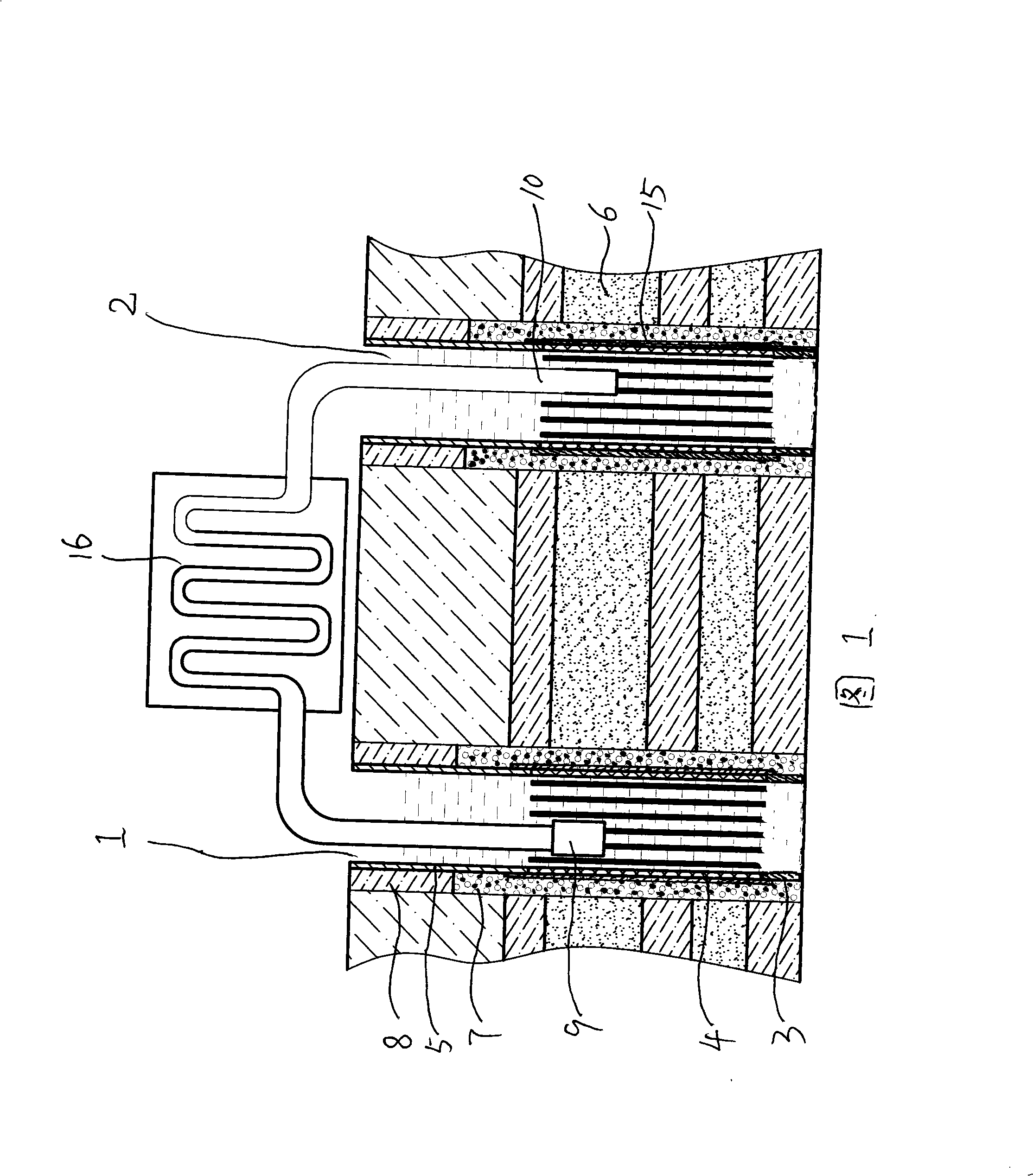
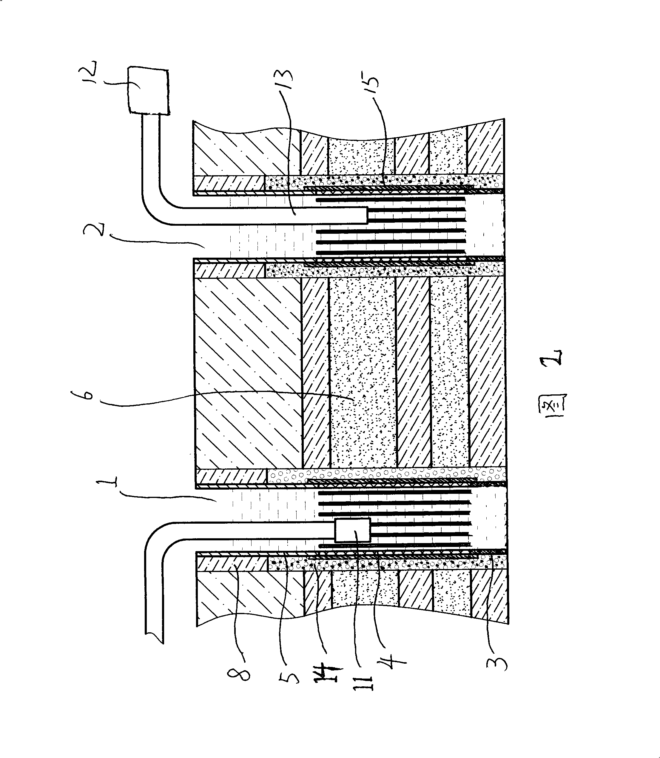
[0045] Embodiment 1: the first step, determine wellbore position and borehole, according to local hydrogeological situation, determine pumping well 1 and reinjection well 2 to be 150 meters, drill pumping well 1 earlier, in the precipitation influence radius of pumping well 1 Drill the wellbore of reinjection well 2 at the 3 / 5 position;

[0046] The second step is to hoist the well pipe, butt and fix the well pipe according to the order of the sedimentation pipe 3, the water filter pipe 4 and the well wall pipe 5, and then put it into the well hole of the pumping well 1 and the well hole of the reinjection well 2 that have been drilled ; And the water filter pipe 4 in the pumping well 1 and the reinjection well 2 is located at the same horizontal position;

[0047] The third step is to fill the filter material. According to the geological structure of the sand layer 6 where the filter pipe 4 is located, a filter material 7 of a corresponding size is selected, and the selected ...

Embodiment 2

[0052] Determine the location of the well hole and drill the well hole. According to the local hydrogeological conditions, determine the pumping well 1 and the reinjection well 2 to be 1000 meters. 2 well holes; and a double-layer 60-mesh filter screen 15 is wound around the filter pipe 4. All the other steps are the same as in Example 1.

Embodiment 3

[0054] Determine the location of the wellbore and drill the wellbore. According to the local hydrogeological conditions, determine the distance between the pumping well 1 and the reinjection well 2 to be 600 meters. 2 well holes; and a double-layer 80-purpose filter screen 15 is wound around the filter pipe 4, and the remaining steps are the same as in Example 1.


PUM


Abstract

The invention belongs to the technical field of the groundwater recharge cyclic utilization method, particularly discloses a groundwater recharge cyclic utilization method, which is characterized by determining the depth of the pumping well and drilling a recharge well borehole having the same depth with the pumping well in the precipitation action radius of the pumping well, according to the local hydrogeology. The well pipe is fixed in the borehole according to the sequence of a sedimentation pipe, a strainer and a case pipe, then filter material, the killing well and the flushing are filled in turn, finally a pumping device and a recharging device are arranged, which forms a circular loop in the water pumping and recharging process. In the flow process of the groundwater, the temperature rises or lowers; and flushing is performed again after killing well, the flushing time is short and complete, and the groundwater does contact with the outside, which does not pollute the groundwater after recharging. The invention not only is suitable for the puaternary system stratal configuration, also suitable for the tertiary stratal configuration of the pottery and the Minghua town.

Description

technical field [0001] The invention belongs to the technical field of groundwater recycling methods, and in particular relates to a groundwater recharge recycling method. Background technique [0002] With the current exploitation and utilization of disposable energy such as coal, oil, natural gas, etc., the energy is less and less, and the cost of exploitation is also higher and higher. People gradually turn their attention to the development of recyclable energy. According to the difference between groundwater temperature and surface temperature, taking advantage of the characteristics that the groundwater temperature is lower than the surface air temperature in summer, the groundwater temperature is higher than the surface air temperature in winter, and the deep groundwater temperature is high, people invented the groundwater air conditioner. After the exchange, it is discharged into the sewer, although it saves energy, it causes a waste of groundwater, especially for de...

Claims


Application Information

Patent Timeline
Patent Type & Authority Applications(China)
IPC IPC(8): F24J3/08
CPCY02E10/10
Inventor 刘娇娜刘金生
Owner 刘娇娜
Learn More