Injector system for combustion engines operated on fuel, in particular heavy oil

A technology of injection system and internal combustion engine, which is applied in the direction of fuel injection device, charging system, liquid fuel feeder, etc., and can solve problems such as damaged operation and failure

Active Publication Date: 2008-11-05
L'ORANGE GMBH
View PDF1 Cites 3 Cited by
  • Summary
  • Abstract
  • Description
  • Claims
  • Application Information

AI Technical Summary

Problems solved by technology

[0007] The risk associated with this is that fuel, mainly heavy oil, can get into one or more combustion chambers during the shutdown of the internal combustion engine, which can lead to serious damage and related malfunctions when starting the internal combustion engine

Method used


Image

  • Injector system for combustion engines operated on fuel, in particular heavy oil
  • Injector system for combustion engines operated on fuel, in particular heavy oil

Examples


Embodiment Construction

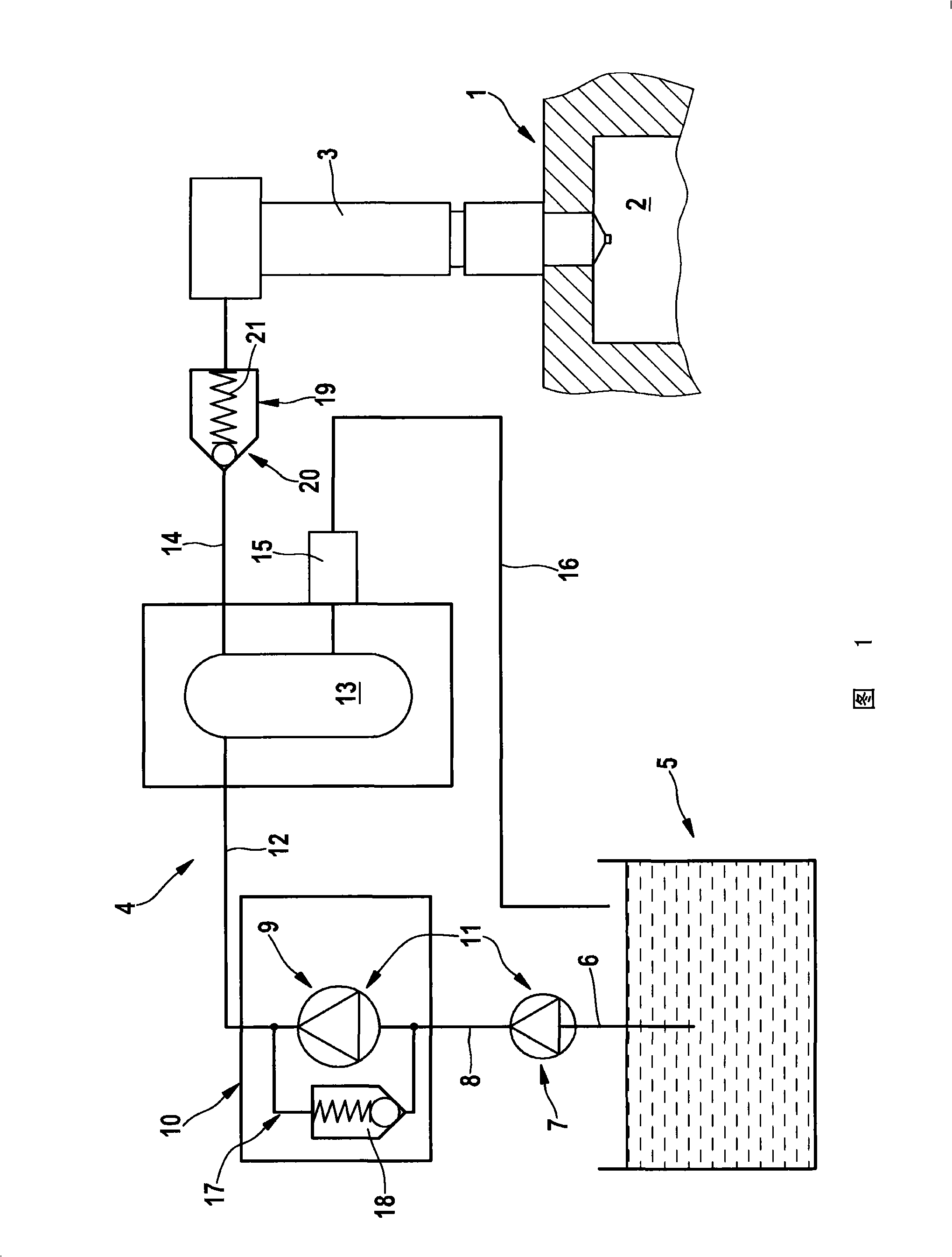
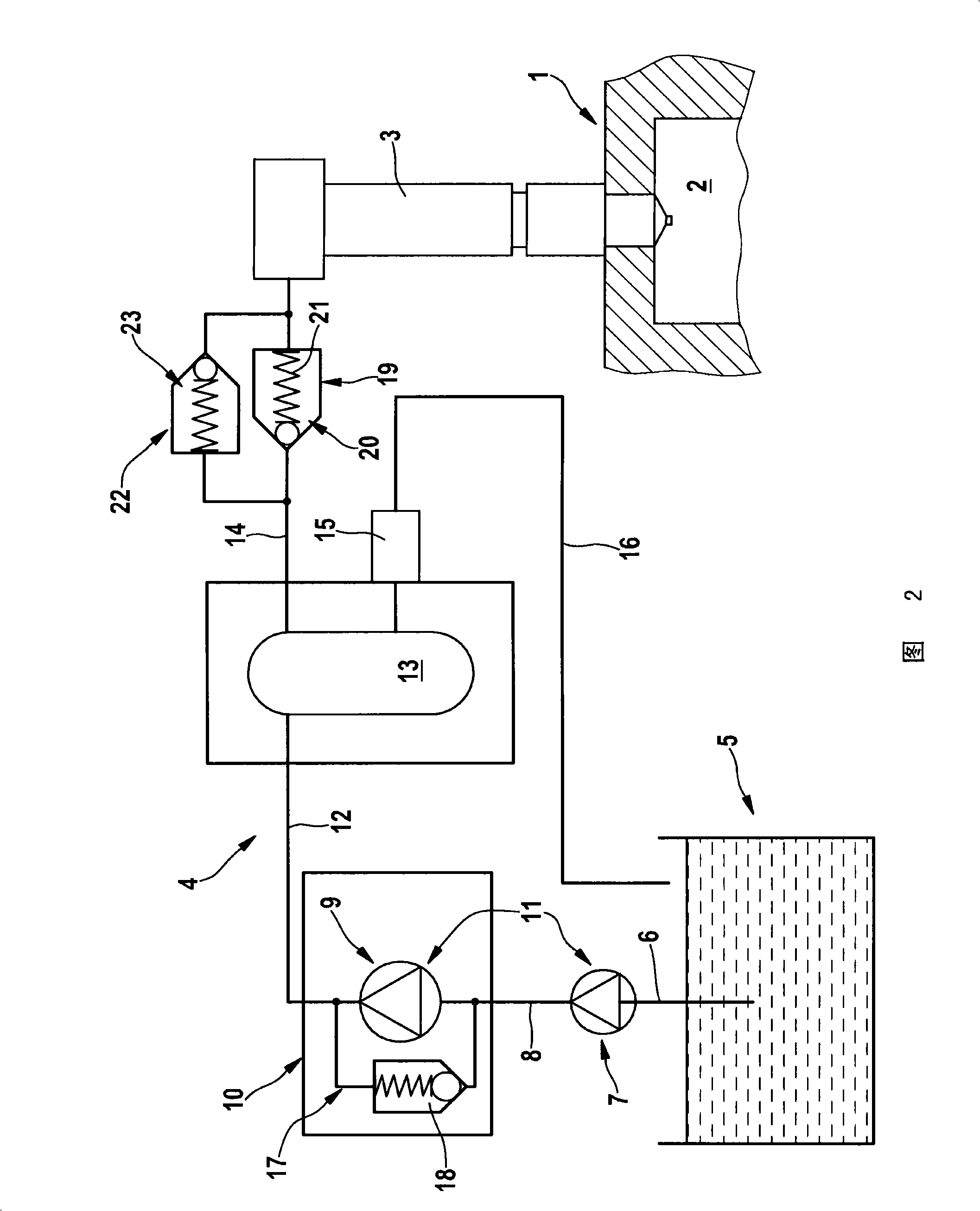
[0016] In view of the fact that the injection systems shown in the schematic views have the same structure in principle, the same reference numerals are used for the same components in the description of FIGS. 1 and 2, where 1 is the internal combustion engine, and only is shown Part of the combustion chamber 2 with one cylinder. Generally, the internal combustion engine 1 is of a multi-cylinder structure and is provided with a corresponding number of injectors 3 similarly to the injectors 3 injected into the combustion chamber 2, which are connected in parallel with the injectors 3 shown here to the overall designation 4 In the injection system.

[0017] The injection system 4 shows its most important elements and starts with a fuel tank 5 for heavy oil set as fuel, including a pre-delivery pump 7 sucked from the fuel tank 5 through a duct 6 as a low-pressure source, and it is connected to a low-pressure source through a duct 8 The high-pressure pump 9 of the high-pressure unit 1...


PUM


Abstract

Injection system comprises a unit (19) lying in a connection of a high pressure storage unit (13) to an injector (3) to release a feed to the injector when the pressure in the high pressure storage unit has exceeded a threshold value lying over the rinsing pressure. Preferred Features: The threshold value lies in pressure region lying at the lower region of the operating pressure. A local pressure storage unit is assigned to the injector.

Description

Technical field [0001] The invention relates to an injection system for an internal combustion engine operating on fuel, in particular heavy oil, according to the preamble of claim 1. Background technique [0002] An injection system of the aforementioned type is disclosed by DE19645243C2. Heavy oil has a high viscosity at ambient temperature and has a consistency approximately similar to that of tar. Accordingly, it needs to be heated to liquefy so that it can be sprayed later. [0003] Correspondingly, the heavy oil must also be maintained at a temperature corresponding to the liquefaction temperature in the injection system to maintain the maneuverability of the system. With regard to the stopped state of the internal combustion engine, that is, the corresponding standstill state of the internal combustion engine, this means that the components associated with the fuel system, including the fuel tank, are kept at a corresponding temperature. This is usually done by using a cor...

Claims


Application Information

Patent Timeline
Patent Type & Authority Applications(China)
IPC IPC(8): F02M63/00F02M37/04F02M47/02
CPCF02M53/02F02M63/0225
Inventor W·谢贝C·森格哈斯
Owner L'ORANGE GMBH
Why Eureka
Try Eureka