
Air pressure type screw nail infiltrating device

An air pressure and driver technology, which is applied in nailing tools, nailing staple tools, motor tools, etc., can solve the problems of increasing the number of parts and the overall height of the tool, reducing the number of parts, easy operation, Get the right depth

Active Publication Date: 2010-05-26
MAX CO LTD
View PDF7 Cites 0 Cited by
  • Summary
  • Abstract
  • Description
  • Claims
  • Application Information

AI Technical Summary

Problems solved by technology

[0005] However, there is a problem that, due to the deformation of a member called a valve stopper that suppresses the stroke of the valve body, the driving force is switched to "strong" even if it is set to "weak", and the overall height of the tool is reduced. High or increased part count

Method used


Image

  • Air pressure type screw nail infiltrating device
  • Air pressure type screw nail infiltrating device
  • Air pressure type screw nail infiltrating device

Examples


Embodiment Construction

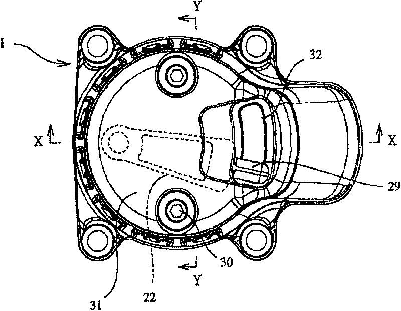
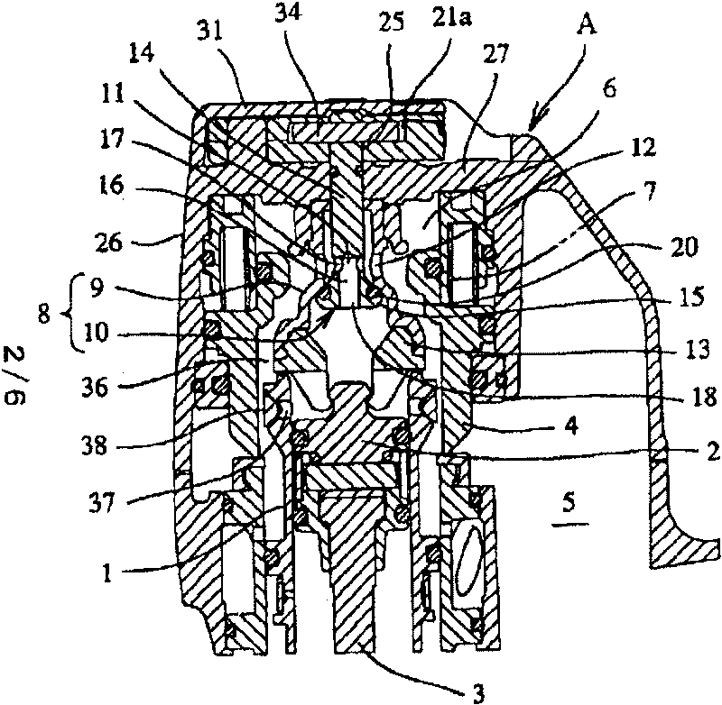
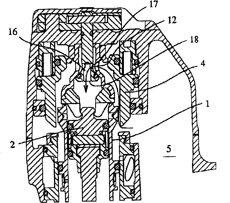
[0044] figure 1 Indicates the upper surface of the screwdriver, Figure 2A and Figure 2B means along figure 1Cross-sectional view of the X-X line. This screw driver has a striking mechanism and a screw tightening mechanism inside the tool body A. As shown in FIG. The percussion mechanism includes a percussion cylinder 1, a percussion piston 2 freely slidably arranged in the percussion cylinder 1, and a screwdriver head 3 integrated with the percussion piston 2, and the main valve 4 is opened by pulling the unillustrated trigger. Action: supply compressed air from the air chamber (connected to the air supply source) 5 storing compressed air to the percussion cylinder 1 to make the screwdriver bit 3 perform the driving action. In addition, a screw tightening mechanism (not shown) drives the screwdriver bit 3 to tighten the screws by power such as an air motor. That is, almost at the same time when the striking mechanism starts to operate, the screw tightening mechanism ope...


PUM


Abstract

A pneumatic screw driving machine comprises an air chamber for reserving a compressed air, a main valve supplying the compressed air reserved in the air chamber to a hammering cylinder, a driver bit for driving and tightening a screw, a valve housing provided in the main valve, and a valve body so provided as to be capable of vertically movable with respect to the valve housing. A through hole opening to the air chamber is formed in the valve housing; and a lower opening part opening to the hammering cylinder, a side opening part opening to the air chamber through the through hole, and a firstair supply passage allowing the lower opening part to communicate with the side opening part are formed in the valve body. When the valve body is moved downward, a second air supply passage allowingthe air chamber to communicate with the hammering cylinder through the through hole is formed between the outer peripheral surface of the valve body on the lower side of the side opening part and theinner peripheral surface of the valve housing.

Description

technical field [0001] The invention relates to an air pressure screw driver. Background technique [0002] In general, an air pressure screwdriver lightly drives a driving screw into a driven part and then firmly tightens it. Corresponding to the process of driving and tightening the screws, the air pressure screw driver is provided with a striking mechanism for striking the driven screws and a screw tightening mechanism for rotating the driven screws. The percussion mechanism is integrated with a screwdriver head on the percussion piston that is slidably accommodated in the percussion cylinder, and the main valve is activated through the operation of the trigger, so that the air chamber storing compressed air is opened and closed relative to the above percussion cylinder, and the impact is directed to the percussion cylinder. The cylinder supplies compressed air to drive the percussion piston. When driving in, the front end of the driving screw needs to penetrate the sur...

Claims


Application Information

Patent Timeline
Patent Type & Authority Patents(China)
IPC IPC(8): B25C7/00B25C1/04B25B21/00
CPCB25B21/023
Inventor 小菅诚春田雅己
Owner MAX CO LTD
Learn More