Method for regulating controllable wave filter

A filter and control signal technology, applied in the direction of impedance network, digital technology network, electrical components, etc., can solve the problems of increased complexity, complex control of adjustable filters, and inability to filter out noise, etc.

Inactive Publication Date: 2008-10-29
MSTAR SEMICON INC
View PDF0 Cites 0 Cited by
  • Summary
  • Abstract
  • Description
  • Claims
  • Application Information

AI Technical Summary

Problems solved by technology

[0005] In the prior art, the practice of distributing the characteristic frequencies of the adjustable filter in different configurations equidistantly in a possible frequency range has its disadvantages
One disadvantage is that the control of the adjustable filter will become more complicated, and the other disadvantage is that when the characteristic frequency is low, the step size of the characteristic frequency of the adjustable filter is smaller than that of the characteristic frequency. If the ratio is too large, it is easy to cause the signal-to-noise ratio (SNR) of the adjustable filter to become poor
[0006] by figure 1 The characteristic frequency distribution diagram shown is an example, since the characteristic frequencies of the adjustable low-pass filter in different configurations are equidistantly distributed between 4MHz and 40MHz (a total of 37 possible characteristic frequencies), so the adjustable The control signal for adjusting the low-pass filter needs to be at least a 6-bit signal, which will increase the complexity of the system for controlling the adjustable low-pass filter
In addition, when the characteristic frequency is equal to 4MHz, its adjacent and larger characteristic frequency is 5MHz, and the step size corresponding to the characteristic frequency of the adjustable low-pass filter is 1MHz at this time, that is, the step size at this time is relatively The ratio of the characteristic frequency is 1MHz / 4MHz=25%, if the data part of the input signal of the adjustable low-pass filter is distributed between 0MHz~4.1MHz on the frequency spectrum, in order to ensure that the data part will not be filtered out, then the adjustable low-pass filter must be controlled to figure 1 The configuration 02 shown (that is, the corner frequency of the adjustable low-pass filter is controlled at 5MHz), however, at this time, it will not be able to filter out the noise distributed between 4.1MHz and 5MHz in the frequency spectrum of the input signal, so As a result, it is bound to degrade the signal-to-noise ratio of the output signal of the adjustable low-pass filter

Method used


Image

  • Method for regulating controllable wave filter
  • Method for regulating controllable wave filter
  • Method for regulating controllable wave filter

Examples


Embodiment Construction

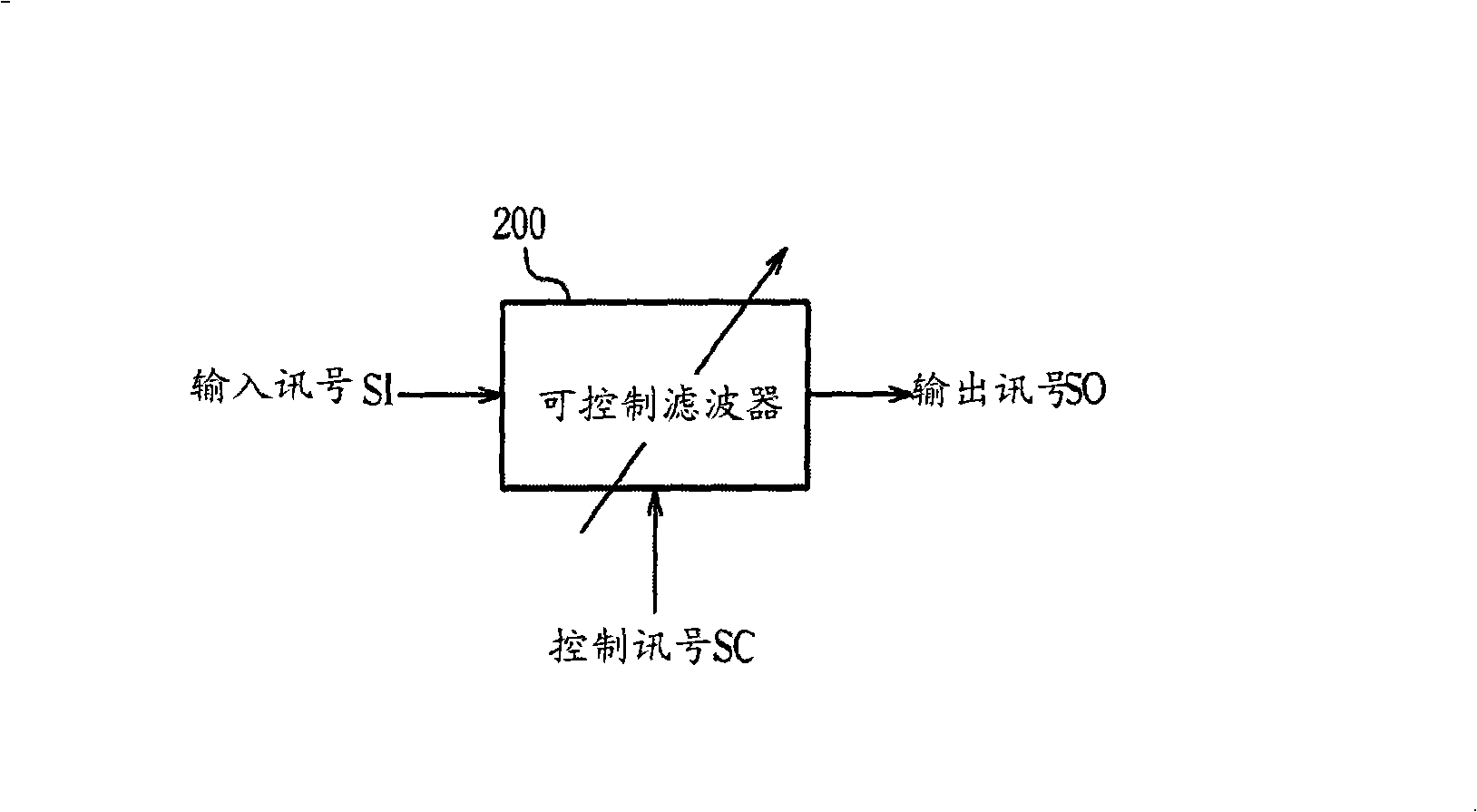
[0015] figure 2 Shown is a schematic diagram of an embodiment of a controllable filter applying the control method of the present invention. The controllable filter 200 of this embodiment is a controllable low-pass filter for low-pass filtering an input signal SI to generate an output signal SO, wherein the frequency response of the controllable filter 200 is controlled by a control signal SC determined by the state.

[0016] The control signal SC is used to control the configuration of the adjustable filter 200. For example, if the adjustable filter 200 is an active RC filter, the control signal SC can be used for the following: Basis for one of the three control modes: 1. Discrete switching (Discrete switching) the resistance in the controllable filter 200, 2. Discrete switching the capacitance in the controllable filter 200, 3. Discrete switching Switching can adjust the resistors and capacitors in the filter 200 . By any one of the aforementioned three control methods,...


PUM


Abstract

The invention discloses a method for adjusting and controlling an adjustable wave filter, which includes that a control signal is input to the adjustable wave filter and the configuration of the adjustable wave filter is adjusted according to the control signal, wherein, when the control signal is in any status of a plurality of preset statuses, one step value of one eigen frequency of the adjustable wave filter is positively related to the eigen frequency of the adjustable wave filter.

Description

technical field [0001] The invention relates to an adjustable filter, in particular to a method for adjusting an adjustable filter. Background technique [0002] A tunable filter is a filter with a tunable frequency response, which is widely used in various electronic devices because it can provide a flexible filtering range. [0003] In general, the frequency response of a tunable filter is determined by the state of its control signal. When the state of the control signal changes, the characteristic frequency (Characteristic frequency) of the adjustable filter will also change accordingly. The aforementioned characteristic frequency refers to the corner frequency (Corner frequency) of an adjustable low-pass (or high-pass) filter, or the pass-band frequency (Pass-band frequency) of an adjustable band-pass filter... . [0004] For the existing controllable filter, the characteristic frequencies under different configurations are equidistantly distributed in a possible fre...

Claims


Application Information

Patent Timeline
Patent Type & Authority Applications(China)
IPC IPC(8): H03H17/00
Inventor 林珩之王富正
Owner MSTAR SEMICON INC
Why Eureka
Try Eureka