
Cutting device for shortening component belts, supply device and automatic loader

A technology of automatic assembly device and cutting equipment, applied in the direction of electrical components, electrical components, metal processing, etc., can solve the problems such as bending and problems of cutting knives or beam-type blades, improve operation reliability, and avoid dust particles. Accumulation, contamination minimization effect

Inactive Publication Date: 2008-10-29
SIEMENS ELECTRONICS ASSEMBLY SYST LLC
View PDF1 Cites 5 Cited by
  • Summary
  • Abstract
  • Description
  • Claims
  • Application Information

AI Technical Summary

Problems solved by technology

This effect can lead to buckling of the cutter or beam blades and is especially problematic with longer cutters

Method used


Image

  • Cutting device for shortening component belts, supply device and automatic loader
  • Cutting device for shortening component belts, supply device and automatic loader
  • Cutting device for shortening component belts, supply device and automatic loader

Examples


Embodiment Construction

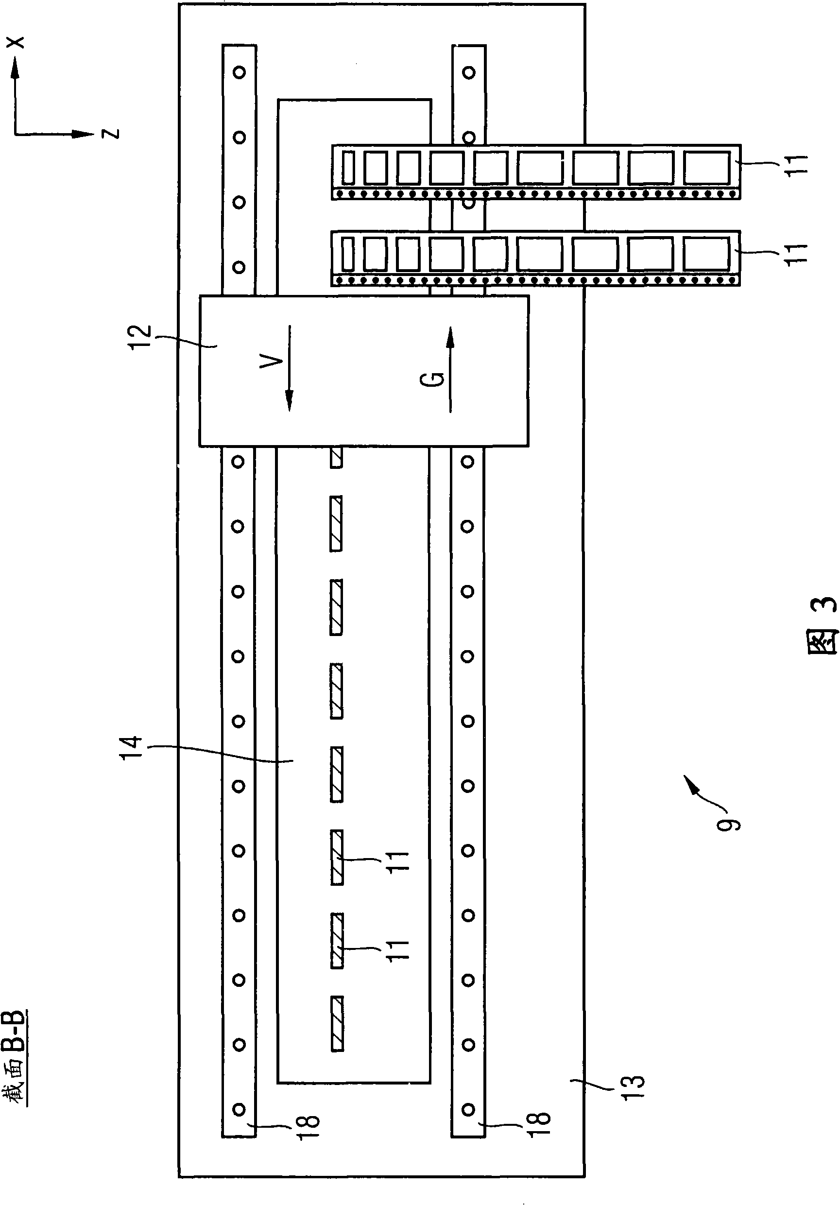
[0051] FIG. 1 schematically shows an automatic assembly device 1 for assembling components 3 for a base plate 2 . The automatic assembly device is formed by a crossbeam 7 which extends in the y-direction and is fixedly connected to the machine frame. Arranged on the transverse beam 7 is a door arm 8 which extends in the x-direction and is fastened displaceably on the transverse beam 7 in the y-direction. Mounting head 6 is mounted displaceably in the x-direction on door arm 8 . Furthermore, a transport path 4 for transporting the substrate 2 to the assembly position is provided. In addition to the transport path 4 , a supply device 5 is arranged in the vicinity of the assembly position, at its defined pick-up position 10 the electronic components 3 in the component strip 11 are supplied. A cutting device 9 for cutting off empty component tapes 11 is arranged between the supply device 5 and the transport path 4 .

[0052] In order to assemble the substrate 2 , it is transpor...


PUM


Abstract

The cutting device for cutting the component belt (11) must be fitted to any cutting length agilely. A cutting device (9) is represented, including a housing (13), a belt passage (14) provided in the housing (13) for the component belt (11) cut short to penetrate in a convey direction (F) and a cutting device (12) moving along a moving direction (V) horizontal to appoint of the convey direction in the housing (13). The cutting device (12) includes a cutting unit (19) and a leaning unit (23), wherein the cutting device has a cutting piece (20) with a cutting blade (21) around capable of rotating and the leaning unit has a leaning piece (24), wherein the cutting unit (19) and the leaning unit (23) act such that the component belt (11) guided in the belt passage (14) is cut horizontal to the convey direction (F) when the cutting device (12) moves.

Description

technical field [0001] The invention relates to a cutting device for shortening component strips, a supply device and an automatic assembly device. Background technique [0002] In an automatic assembly device for assembling a substrate with electronic components, the components are supplied by a supply device provided on the automatic assembly device. Electronic components are often stored in pocket-like pockets on relatively long component tapes. The component strips are transported through the supply device by means of the transport mechanism of the supply device, wherein the components are removed from the recesses by the assembly head of the automatic assembly device in the pick-up position. Empty component strips leave the supply unit to a suitable location. In this case, the necessity arises to cut the empty component tapes at specific intervals after they have emerged from the supply device, so that the remaining waste material is in a form that can be disposed of....

Claims


Application Information

Patent Timeline
Patent Type & Authority Applications(China)
IPC IPC(8): B26D1/14B26D5/08B26D7/06H05K13/00
CPCB26D1/22B26D5/02B26D7/02B26D1/24
Inventor 罗伯特·康拉德穆罕默德·迈赫迪安普
Owner SIEMENS ELECTRONICS ASSEMBLY SYST LLC
Learn More