
Motor and control circuit thereof

A technology for controlling circuits and currents, which is applied in the direction of AC motor control, control systems, electrical components, etc., and can solve the problems of inability to apply high-speed or large-size motors and high cost

Active Publication Date: 2010-12-22
DELTA ELECTRONICS INC
View PDF4 Cites 0 Cited by
  • Summary
  • Abstract
  • Description
  • Claims
  • Application Information

AI Technical Summary

Problems solved by technology

[0005] As mentioned above, as far as the traditional motor is concerned, a group of control circuits only has one sensing chip, so one sensing chip needs to control the winding group of the entire motor to provide the current required by each winding, and because the general sensing chip The test chip cannot withstand excessive current, so this control circuit cannot be applied to high-speed or large-size motors
For sensing chips used in high-speed or large-size motors, they must have greater current carrying capacity, which usually requires a higher-cost sensing chip

Method used


Image

  • Motor and control circuit thereof
  • Motor and control circuit thereof
  • Motor and control circuit thereof

Examples


Embodiment Construction

[0030] A motor and its control circuit according to preferred embodiments of the present invention will be described below with reference to the relevant drawings.

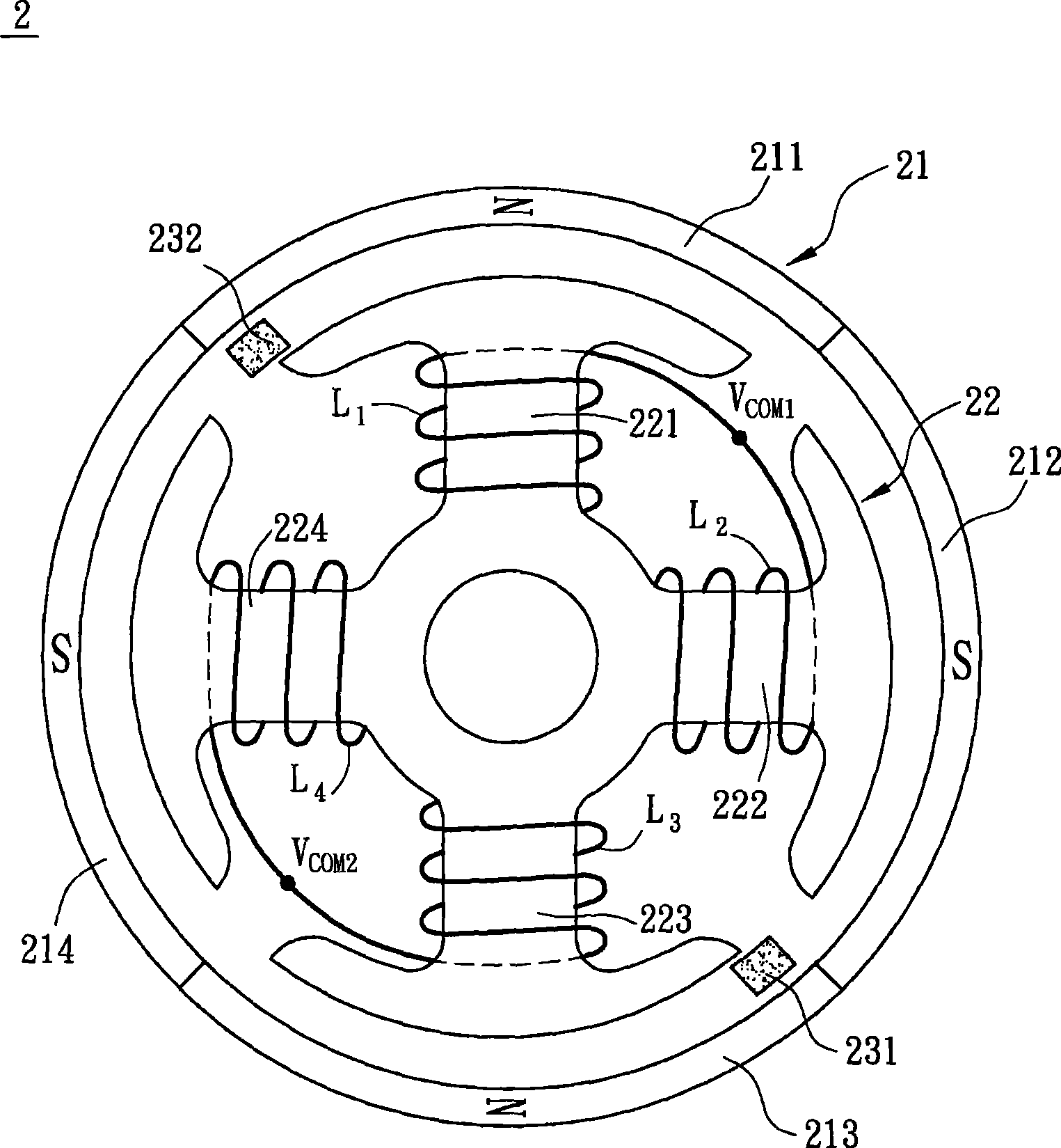
[0031] Please refer to image 3 and Figure 4 as shown, image 3 is a schematic diagram of a motor 2 according to a preferred embodiment of the present invention, and Figure 4 is a perspective view of the motor 2. The motor 2 includes a rotor 21 , a stator 22 and a control circuit 23 .

[0032] The rotor 21 has a plurality of magnetic poles, and the magnetic poles are arranged alternately by N poles and S poles. In this example, the rotor 21 has four magnetic poles 211 , 212 , 213 and 214 , wherein 211 and 213 are N poles, and 212 and 214 are S poles.

[0033] The stator 22 is formed by stacking a plurality of silicon steel sheets, wherein each silicon steel sheet has at least two induction arms, and the induction arms of the silicon steel sheets are respectively arranged opposite to the magnetic poles, for ...


PUM


Abstract

The invention discloses a control circuit of a motor comprising at least two sensing chips and at least two groups of winding groups, wherein the sensing chips are connected electrically with each other, and the winding groups respectively comprise a first winding and a second winding, one end of the first winding is connected with one end of the second winding electrically, while the other endsof the first winding and the second winding are electrically connected with the corresponding sensing chips. In addition, the invention also discloses a motor with the control circuit.

Description

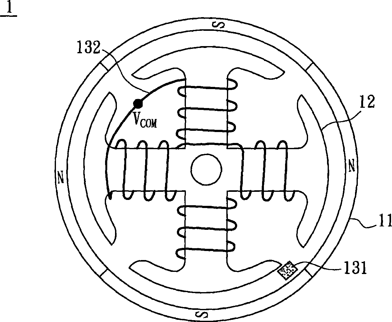
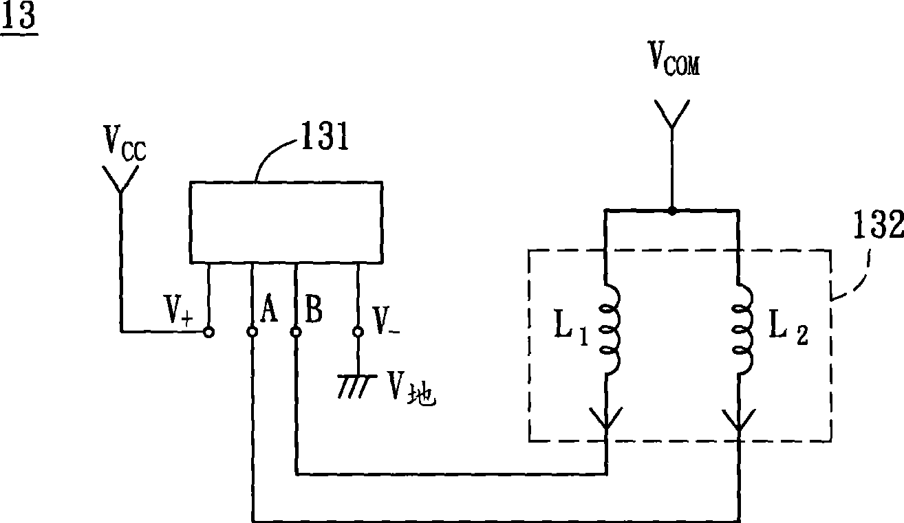
technical field [0001] The present invention relates to a motor and its control circuit, in particular to a motor controlled by multiple sensing chips and its control circuit. Background technique [0002] Please refer to figure 1 As shown in , it is a schematic diagram of a conventional motor 1 . The motor 1 has a rotor 11 and a stator 12 . The rotor 11 has a plurality of magnetic poles, including two N poles and two S poles, and the N poles and the S poles are arranged alternately. The stator 12 is formed by stacking a plurality of silicon steel sheets, and the stator 12 has a plurality of winding arms opposite to the magnetic poles. [0003] Then please refer to figure 2 As shown, it is a schematic diagram of a control circuit 13 of the conventional motor 1 . The control circuit 13 includes a sensing chip 131 and a winding group 132, wherein the sensing chip 131 of the control circuit 13 has a positive power input terminal V+ and a negative power input terminal V-, ...

Claims


Application Information

Patent Timeline
Patent Type & Authority Patents(China)
IPC IPC(8): H02K11/00H02P25/16H02K11/20
Inventor 陈李龙沈基成
Owner DELTA ELECTRONICS INC
Learn More