
Vehicle with a frame and a cabin

A cab, vehicle technology, applied in vehicle components, superstructure of trucks, transportation and packaging, etc., can solve problems such as reduction of pitching motion

Inactive Publication Date: 2008-10-15
CARL FREUDENBERG KG
View PDF0 Cites 5 Cited by
  • Summary
  • Abstract
  • Description
  • Claims
  • Application Information

AI Technical Summary

Problems solved by technology

Particularly with short cabs, a reduction in pitching motions can currently only be achieved by means of complex measures

Method used


Image

  • Vehicle with a frame and a cabin
  • Vehicle with a frame and a cabin
  • Vehicle with a frame and a cabin

Examples


Embodiment Construction

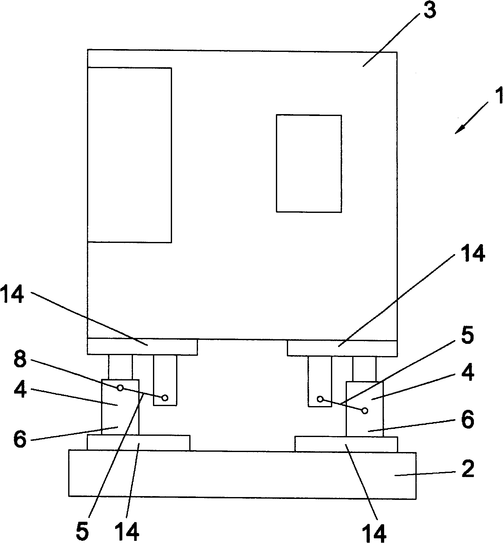
[0028] figure 1 Shown is a vehicle 1, agricultural implement or construction machine, comprising a frame 2 and a driver's cab 3, which are connected to each other via elastic and damping bearings 4 - here hydraulic bearings. connect. Four bearings 4 , here designed as hydrodynamic bearings, are provided for this purpose. Between the frame 2 and the driver's cab 3 a rod 5 is arranged for each support element 4 , which is articulated to the frame 2 and the driver's cab 3 in such a way that the pivoting of the driver's cab 3 is reduced. To this end, each rod 5 is assigned to a respective support part 4 and is articulately connected to a part 6 of the support part 4 which is fixed rigidly to the vehicle frame 2 or, in another embodiment, to the driver's cab 3 .

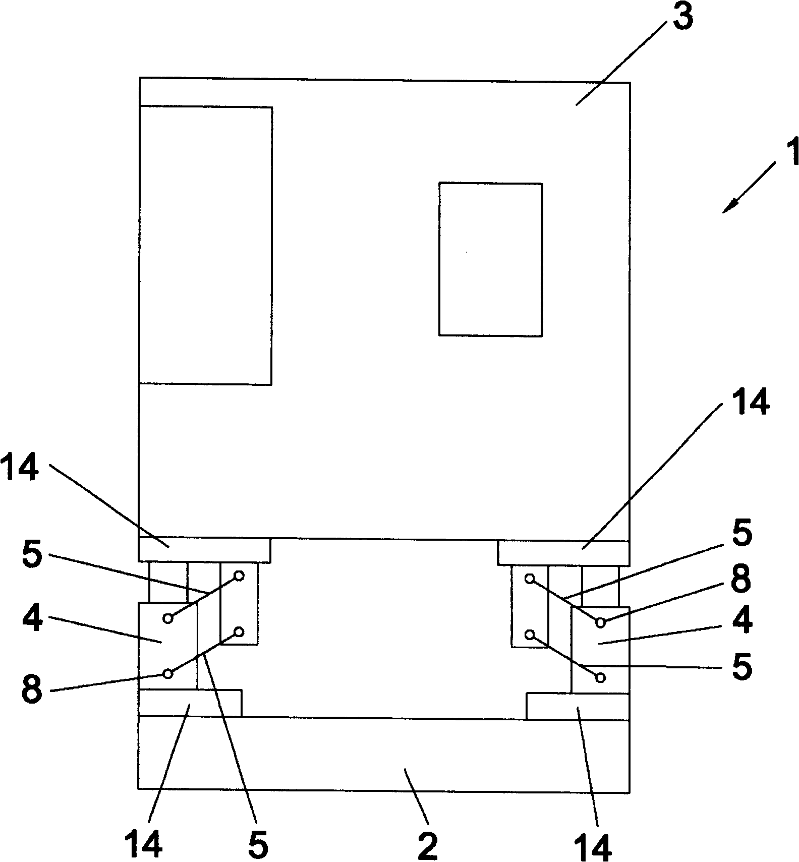
[0029] figure 2 show the basis figure 1 A form of implementation, wherein each support 4 is provided with two rods 5 that are hingedly connected to the support 4 and the cab 3 .

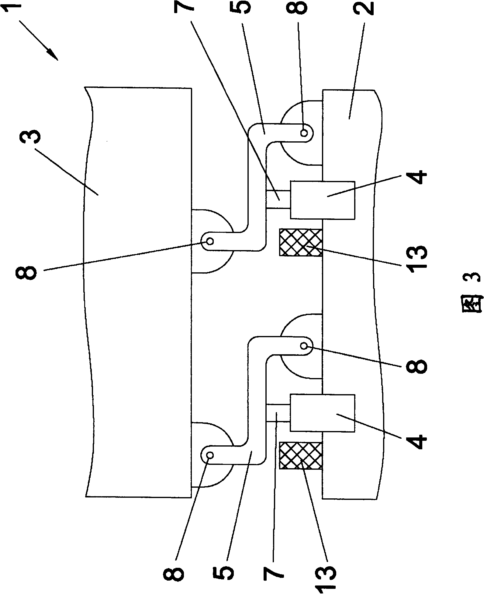
[0030] Figure 3 shows the basis of ...


PUM


Abstract

The vehicle (1) has a frame (2) and a cabin (3) connected with each other by a spring-loaded and / or damping bearing (4). A rod (5) is provided between the frame and the cabin and is arranged with the frame and the cabin in an articulated manner such that an oscillating movement of the cabin is reduced. The rod is assigned to the bearing and is connected with a section (6) of the bearing in an articulated manner, where the bearing is rigidly fastened to the frame or the cabin. A movable support of the bearing is connected with the rod.

Description

technical field [0001] The invention relates to a vehicle with a frame and a cab, which are connected to each other by elastic and / or damping supports. Background technique [0002] The driver's cab of a vehicle, in particular an agricultural implement or a construction machine, can be fastened to the vehicle frame via various support structures. The support structure should be as soft as possible in order to achieve a high vibration isolation effect. However, when the supporting structure is relatively soft, there is a problem that the cab is prone to pendulum movement during acceleration. Here, the lateral swing of the cab is called roll, while the longitudinal swing of the cab is called pitch. Rolling motions occur in particular when driving in curves, while pitching motions are produced in particular by acceleration and braking processes. It is known to stabilize the driver's cab by means of roll bearings in order to avoid roll movements. In particular with short cab...

Claims


Application Information

Patent Timeline
IPC IPC(8): B62D33/10
CPCB62D33/0604
Inventor A·埃尔D·居特勒R·哈克T·乔斯克T·S·阿斯平
Owner CARL FREUDENBERG KG
Learn More