Three-axis six-freedom degree vibration test apparatus
A technology of vibration test and degree of freedom, which is applied in the direction of vibration test, measuring device, machine/structural component test, etc. It can solve the cumbersome and time-consuming operation, the inaccurate evaluation of product vibration performance, and the inability to simulate the simultaneous action of three axes and six degrees of freedom Problems such as complex vibration environment and other problems, to achieve the effect of improving accuracy and efficiency
- Summary
- Abstract
- Description
- Claims
- Application Information
AI Technical Summary
Problems solved by technology
Method used
Image
Examples
Embodiment 1
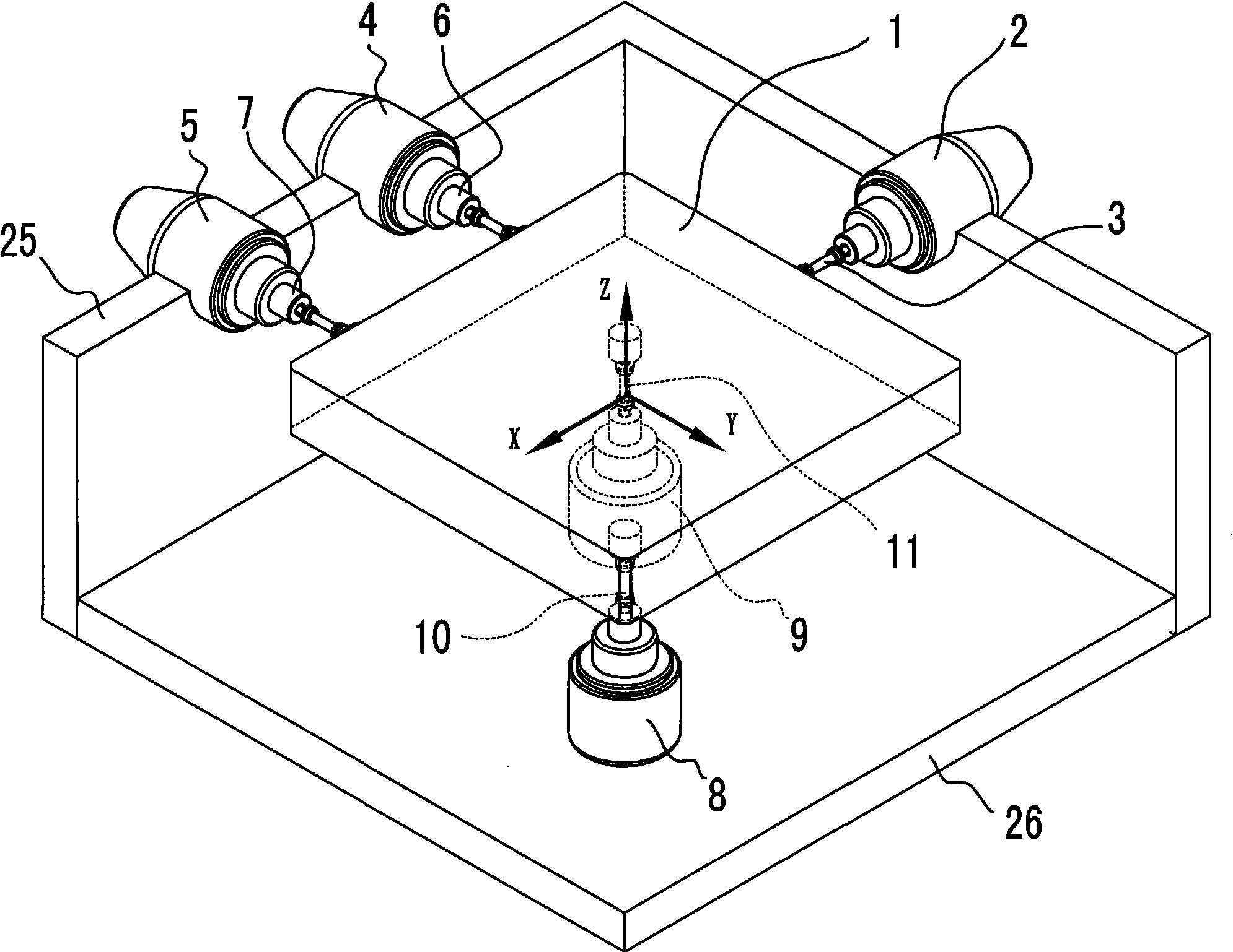
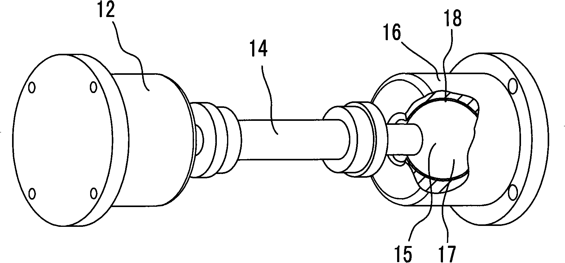
[0033] Embodiment one: see attached figure 1 ~ attached image 3 As shown, a three-axis six-degree-of-freedom vibration test device includes a test piece workbench 1, with the center of gravity of the test piece workbench 1 as the coordinate origin, and a first vibration generator 2 is set in the horizontal X-axis direction. The vibration generator is an electric vibration table, and the vibrating body of the vibration generator (i.e. the moving coil of the electric vibration table) is connected to the side of the test piece table 1 through the first spherical connector 3, and the first vibration generator 2 The central axis of the vibrating body (that is, the moving coil) is coincident with the horizontal X-axis; the second vibration generator 4 and the third vibration generator 5 are arranged side by side in the direction of the horizontal Y-axis, and these two vibration generators are also electric vibration tables , they are symmetrical about the Y axis, and the central a...
Embodiment 2
[0045] Embodiment two: see attached Figure 4 As shown, a three-axis six-degree-of-freedom vibration test device includes a test piece workbench 1. The difference from Embodiment 1 is that the center of gravity of the test piece workbench 1 is used as the origin of coordinates, and in the direction of the horizontal X-axis Also be provided with the 6th vibrating generator 19, this vibrating generator and the first vibrating generator 2 are symmetrical with the X axis, and both central axes are arranged in the same horizontal plane passing the origin, the vibrating body of the 6th vibrating generator 19 It is connected with the test piece table 1 through the sixth spherical connector 20; the seventh vibration generator 21 and the eighth vibration generator 22 are arranged side by side in the Z-axis direction, and these two vibration generators are respectively located on the X-axis and In the other two diagonal phases (specifically the second quadrant and the fourth quadrant) o...
Embodiment 3
[0049] Embodiment three: see attached Figure 5 As shown, a three-axis six-degree-of-freedom vibration test device includes a test piece workbench 1. The difference from Embodiment 1 is that the coordinate system defines direction changes. As shown in the figure, Embodiment 1 is now defined The Y-axis in the central plain is the X-axis, the original X-axis is the Y-axis, and the positions of the first vibration generator 2, the second vibration generator 4, and the third vibration generator 5 are exchanged with the change of the coordinate system; The four vibration generators 8 and the fifth vibration generator 9 are respectively located in the second quadrant and the fourth quadrant divided by the X axis and the Y axis.
[0050] Others are the same as those in Embodiment 1, and will not be repeated here. The working process of this embodiment can be summarized from the aforementioned first and second embodiments, and will not be repeated here.
PUM
 Abstract
Description
Claims
Application Information
 - R&D Engineer
- R&D Manager
- IP Professional
- Industry Leading Data Capabilities
- Powerful AI technology
- Patent DNA Extraction
Browse by: Latest US Patents, China's latest patents, Technical Efficacy Thesaurus, Application Domain, Technology Topic, Popular Technical Reports.
© 2024 PatSnap. All rights reserved.Legal|Privacy policy|Modern Slavery Act Transparency Statement|Sitemap|About US| Contact US: help@patsnap.com


