
Knitting needle of computer flat knitting machine

A flat knitting machine and knitting needle technology, which is applied in knitting, weft knitting, textile and paper making, etc., can solve the problems of high driving power of the machine head, increase the manufacturing cost, increase the floor space, etc., and reduce the volume and is not easy to wear. , the effect of saving manufacturing costs

Inactive Publication Date: 2008-10-08
JIANGSU JINLONG TECHNOLOGY CO LTD
View PDF1 Cites 8 Cited by
  • Summary
  • Abstract
  • Description
  • Claims
  • Application Information

AI Technical Summary

Problems solved by technology

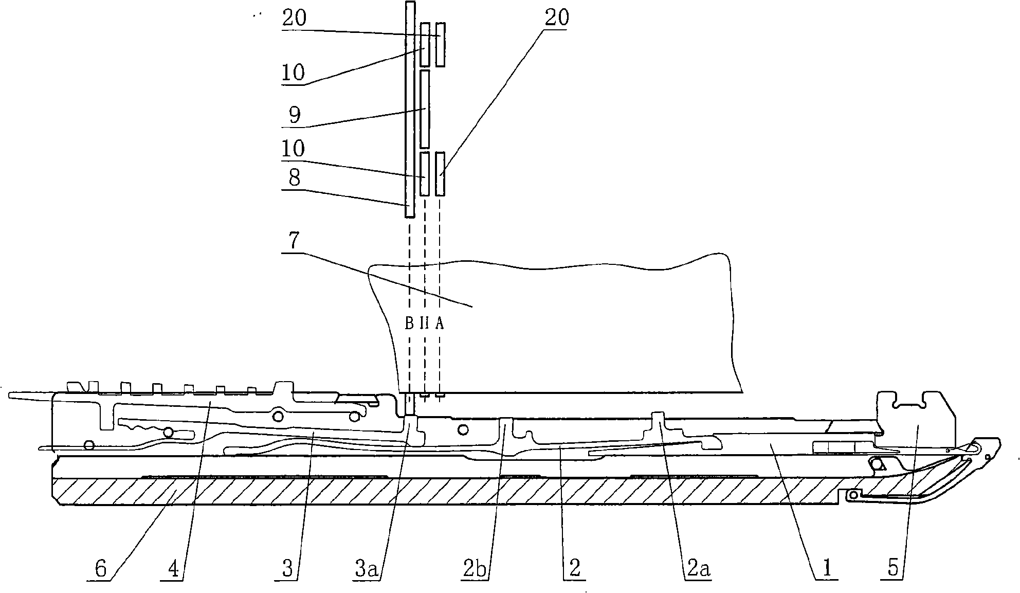
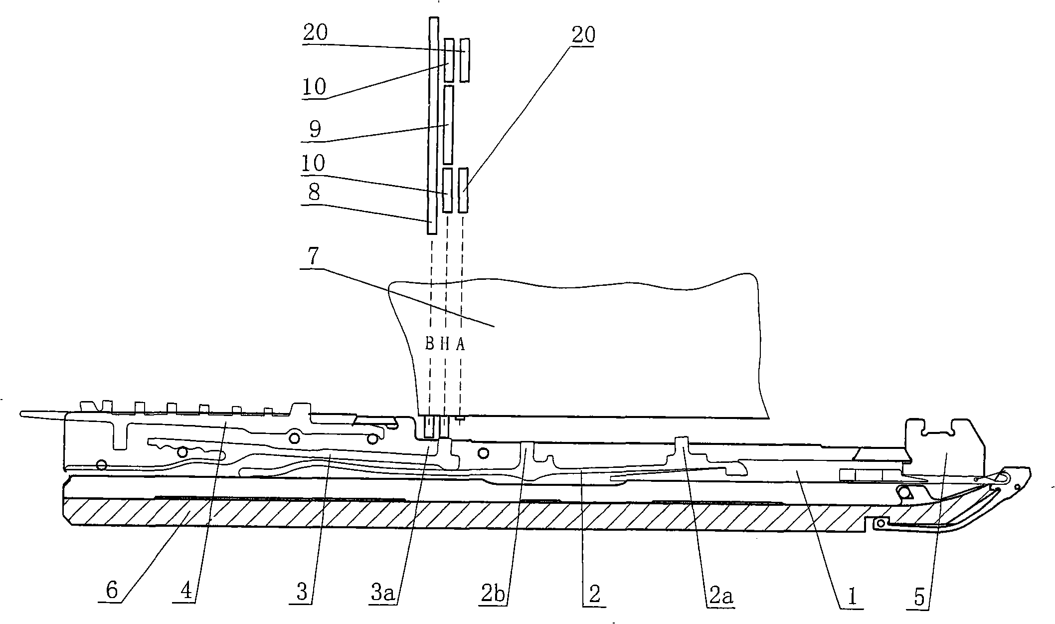
[0009] Analyzing the working principle of the knitting needle assembly of the existing computerized flat knitting machine, it can be seen that the knitting needle assembly of the existing computerized flat knitting machine has a large number of components, which are composed of a knitting needle 1, a lifting pin 2, a push piece 3, and a selection pin 4. In addition, in order to meet the needs of pressing the butt 2b into the needle groove, the lifter 2 must be processed into a slender shape, which leads to an increase in the size of the needle bed 6 along the running direction of the knitting needle 1, which in turn leads to the size of the head 7 and the entire machine. Increase, increase floor space, increase manufacturing cost
When the butt 3a of the push piece 3 of the existing computerized flat knitting machine is pressed into the needle groove, it needs to overcome the elastic force of the lifter pin 2, and the resistance is relatively large, which leads to the non-woven pressing of the push piece 3 on the butt 3a. 8. The tuck pressing piece 9 and the needle pressing piece 10 are easy to wear, and the driving power of the machine head is large
The tuck presser 9, the pin presser 10 and the second-stage stitch presser 20 acting on the butt 3a of the pusher 3 require a complex mechanism combined with program control, which increases the manufacturing cost and difficulty

Method used


Image

  • Knitting needle of computer flat knitting machine
  • Knitting needle of computer flat knitting machine
  • Knitting needle of computer flat knitting machine

Examples


Embodiment Construction

[0034] In order to enable the examiners of the patent office, especially the public, to understand the technical essence of the present invention more clearly, and to make the advantages and effects of the present invention clearer, the applicant will describe the specific implementation of the present invention in detail below in conjunction with the accompanying drawings , but all descriptions of the implementation manners shall not be regarded as limitations on the solutions of the present invention, and any equivalence changes in form but not in substance shall be deemed to belong to the scope of the technical solutions disclosed in the present invention.

[0035] please see Figure 5, taking the current illustrated position state as an example, the structure and function of the hook head 14 at the right end of the knitting needle 1 have no difference from the prior art, and as one of the specific means in the technical solution of the present invention, it is in this knitt...


PUM


Abstract

A needle component of a computer cross-knitting machine belongs to the knitting structure technology field of computer cross-knitting machine, which is composed of a needle, a pin bottom and a selective pin bottom. The lower part of the needle close to the middle is opened with a the first gap in which the entrance is extended with the first flange, and the lower surface of the rear end part of the needle is in the formation of the first titled face. The end of one end of the pin bottom is in the formation of the second flange, and the upper part of the adjacent part of the second flange is opened with a second gap. The upper surface of the middle part of the pin bottom is in the formation of the second titled face matched with the first titled one. The other end of the pin bottom is in the formation of an upper needle butt and a lower needle butt, and the side of the upper needle butt is extended with an actuating flange. Therefore, the invention has the advantages that the size of the entire computer cross-knitting machine is reduced to facilitate the installation and the saving of costs. The nose has a simple structure, which is not easy to wear. Thus the density of clothing can be remained stable.

Description

technical field [0001] The invention relates to a knitting needle assembly of a computerized flat knitting machine, which is used for knitting yarn into clothes, and belongs to the technical field of knitting mechanisms of a computerized flat knitting machine. Background technique [0002] The knitting needle assembly of the computerized flat knitting machine is the executive component that knits the yarn into clothes. Its working principle determines the working principle and performance of the machine head that drives the knitting needle assembly, and affects the performance and performance of the computerized flat knitting machine. Cost of production. [0003] figure 1 It is a cross-sectional schematic diagram of a prior art computerized flat knitting machine in which the knitting needle assembly is arranged on a needle bed, and it includes: knitting needle 1 , jacking pin 2 , push piece 3 , and stitch selection pin 4 . The knitting needle 1, the jacking pin 2, the push...

Claims


Application Information

Patent Timeline
IPC IPC(8): D04B15/00D04B35/02
Inventor 金永良付洪平
Owner JIANGSU JINLONG TECHNOLOGY CO LTD
Learn More