Roll stand provided with a displacement device

A technology of rolling mill stand and rolling mill stand, which is applied in the direction of metal rolling mill stand, driving device for metal rolling mill, metal rolling stand, etc. The effect of improved proximity, simple axial positioning

Inactive Publication Date: 2008-10-01
西门子VAI金属技术有限责任公司
View PDF1 Cites 6 Cited by
  • Summary
  • Abstract
  • Description
  • Claims
  • Application Information

AI Technical Summary

Problems solved by technology

The disadvantage is that an additional and expensive roll shifter is still required

Method used


Image

  • Roll stand provided with a displacement device
  • Roll stand provided with a displacement device
  • Roll stand provided with a displacement device

Examples


Embodiment Construction

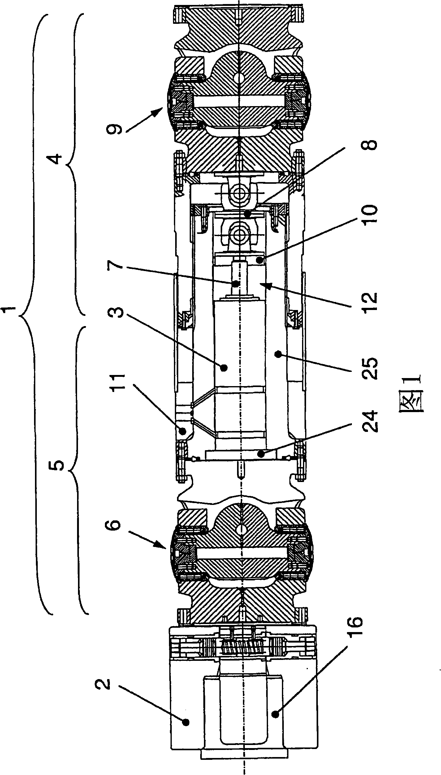
[0036] FIG. 1 shows a transmission shaft ( 1 ) with two shaft parts ( 4 ) and ( 5 ) in section. The shaft part (4) is arranged stationary on the motor side, while the shaft part (5) is arranged displaceable in the axial direction. The drive shaft (1) serves to drive the rollers, wherein height position offsets and axial position changes can be compensated accordingly via the drive shaft (1). The shaft (1) shown has two joints (6, 9). A piston-cylinder unit (3) is arranged in the recess (12) for axially displacing the movable shaft part (5), wherein the cylinder is fixed by means of a cylinder flange (24) to the joint head (6) and Between the drive shaft inner parts (25). The piston rod (7) is guided radially within the drive shaft inner part (25) by means of a guide disc (10). The piston rod (7) is connected to the joint head (9) via the guide disc (10) and the connecting joint (8), wherein unavoidable axial offsets can be compensated and thus avoid damage to the piston-cyl...


PUM


Abstract

The invention relates to a roll stand comprising at least one pair of rollers mounted on a stand frame, drive shafts (1), in particular articulated shafts, for rotatably driving the rollers and a coupling device (2) for coupling the drive shafts (1) and rollers. The invention also relates to a novel axial roller displacement based on the drive shaft (1) which is provided with a roller actuating device (3). A method for axially displacing the rollers is also disclosed.

Description

technical field [0001] The invention relates to a rolling mill stand with at least one pair of rolls supported in the rolling mill stand; a drive shaft, in particular a coupling shaft, for driving the rolls in rotation; and a coupling device for coupling the drive shaft and the rollers. Furthermore, the invention relates to a method for axially displacing at least one roll of a roll pair driven in rotation by a transmission shaft, said roll being supported in said roll stand by means of a plurality of inserts, wherein said roll The axial movement is carried out together with these inserts. Background technique [0002] Various axial roll shifting devices are known in the prior art. In order to influence the cross-section of the rolled material (also expressed as: rolled material shape), the following is known: the roll is moved in the axial direction and at the same time the rolling is influenced in a targeted manner by the shape of the roll or its deformation behavior. T...

Claims


Application Information

Patent Timeline
Patent Type & Authority Applications(China)
IPC IPC(8): B21B35/14B21B31/18F16C3/03
CPCF16C3/03B21B31/18B21B35/143F16C2322/12B21B35/14
Inventor 鲁道夫·朗格德
Owner 西门子VAI金属技术有限责任公司
Why Eureka
Try Eureka