


Quick Research
Generate reliable direction feasibility study reports for your R&D in just a few steps.

Technical Q&A
Discover and master advanced knowledge NOW. Basics, ideas, possibilities, all at once.

Find Solutions
As an expert in R&D theories, this can generate solutions to your technical problems instantly.

Evaluate Feasibility
Analyze your overall solution with one click, know your potential R&D risks in advance.

Monitor Landscape
Get weekly tech updates, stay abreast of the latest tech innovations and key insights.
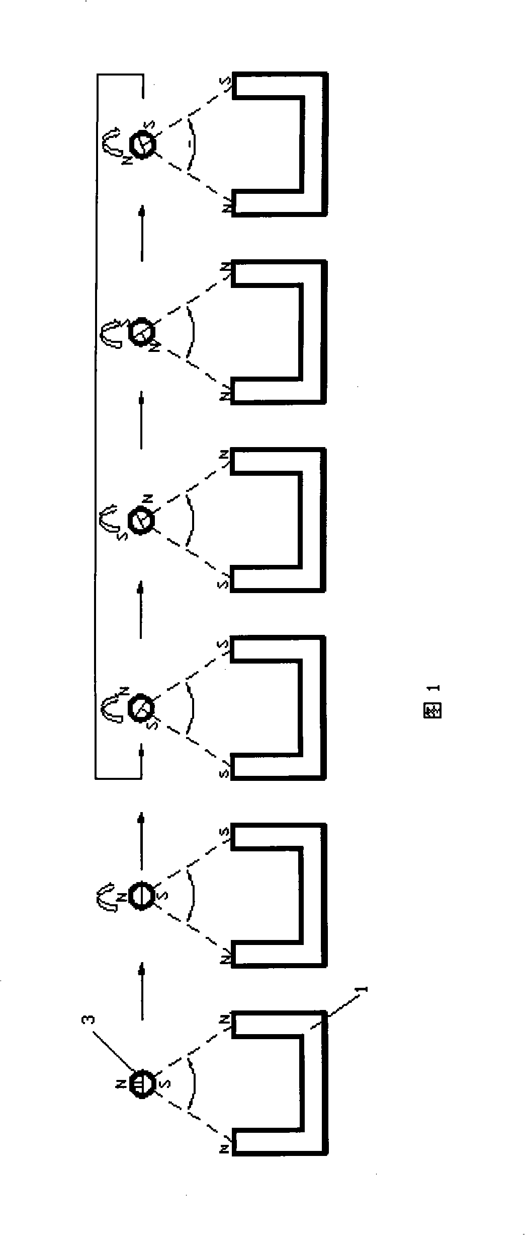
Non-contact type large clearance magnetically-actuated method
A magnetic drive, non-contact technology, applied in the direction of magnetic core/yoke, generator/motor, electrical components, etc., can solve the problems that the normal operation of the drive system cannot be guaranteed, and the motor is easily damaged, so as to improve the effective drive gap, The effect of simple process method and simplified structure
- Summary
- Abstract
- Description
- Claims
- Application Information
AI Technical Summary
Problems solved by technology
Method used
Image

Examples
Embodiment 1
[0033] U78 iron core is used, the length of the iron core is 78mm, the diameter of the coil wire is 0.31mm, the number of turns is 650 turns, the current is 1A, the inner diameter of the permanent magnet is 2mm, the outer diameter is 8.2mm, the axial length is 15mm, and the material is NdFeB N50. When the coupling distance between the electromagnet and the permanent magnet is 30mm, the coaxial micro blood pump can be driven by the permanent magnet to form a water flow circulation in the water pipe with a water column height of 590mm and an inner diameter of 20mm;
Embodiment 2
[0035] U78 iron core is used, the length of the iron core is 78mm, the diameter of the coil wire is 0.31mm, the number of turns is 650 turns, the current is 1A, the inner diameter of the permanent magnet is 2mm, the outer diameter is 8.2mm, the axial length is 15mm, and the material is NdFeB N50. When the coupling distance between the electromagnet and the permanent magnet is 45mm, the coaxial micro blood pump can be driven by the permanent magnet to form a water circulation in the water pipe with a height of 550mm and an inner diameter of 20mm;
Embodiment 3
[0037]U78 iron core is used, the length of the iron core is 78mm, the diameter of the coil wire is 0.31mm, the number of turns is 650 turns, the current is 1A, the inner diameter of the permanent magnet is 2mm, the outer diameter is 8.2mm, the axial length is 15mm, and the material is NdFeB N50. When the coupling distance between the electromagnet and the permanent magnet is 60 mm, the coaxial micro-blood pump is driven by the permanent magnet to form a water flow circulation in a water pipe with a water column height of 500 mm and an inner diameter of 20 mm.
PUM
 Abstract
Description
Claims
Application Information
 - R&D Engineer
- R&D Manager
- IP Professional
- Industry Leading Data Capabilities
- Powerful AI technology
- Patent DNA Extraction
Browse by: Latest US Patents, China's latest patents, Technical Efficacy Thesaurus, Application Domain, Technology Topic, Popular Technical Reports.
© 2024 PatSnap. All rights reserved.Legal|Privacy policy|Modern Slavery Act Transparency Statement|Sitemap|About US| Contact US: help@patsnap.com