
Method and device for utilizing flow separated from oil gas water separator for integral generation

A separator, oil-gas-water technology, applied in the directions of hydropower generation, fluid extraction, safety devices, etc., can solve the problem of energy waste of separators, and achieve the effect of reducing consumption and realizing energy saving and emission reduction.

Inactive Publication Date: 2008-09-17
文立刚
View PDF0 Cites 19 Cited by
  • Summary
  • Abstract
  • Description
  • Claims
  • Application Information

AI Technical Summary

Problems solved by technology

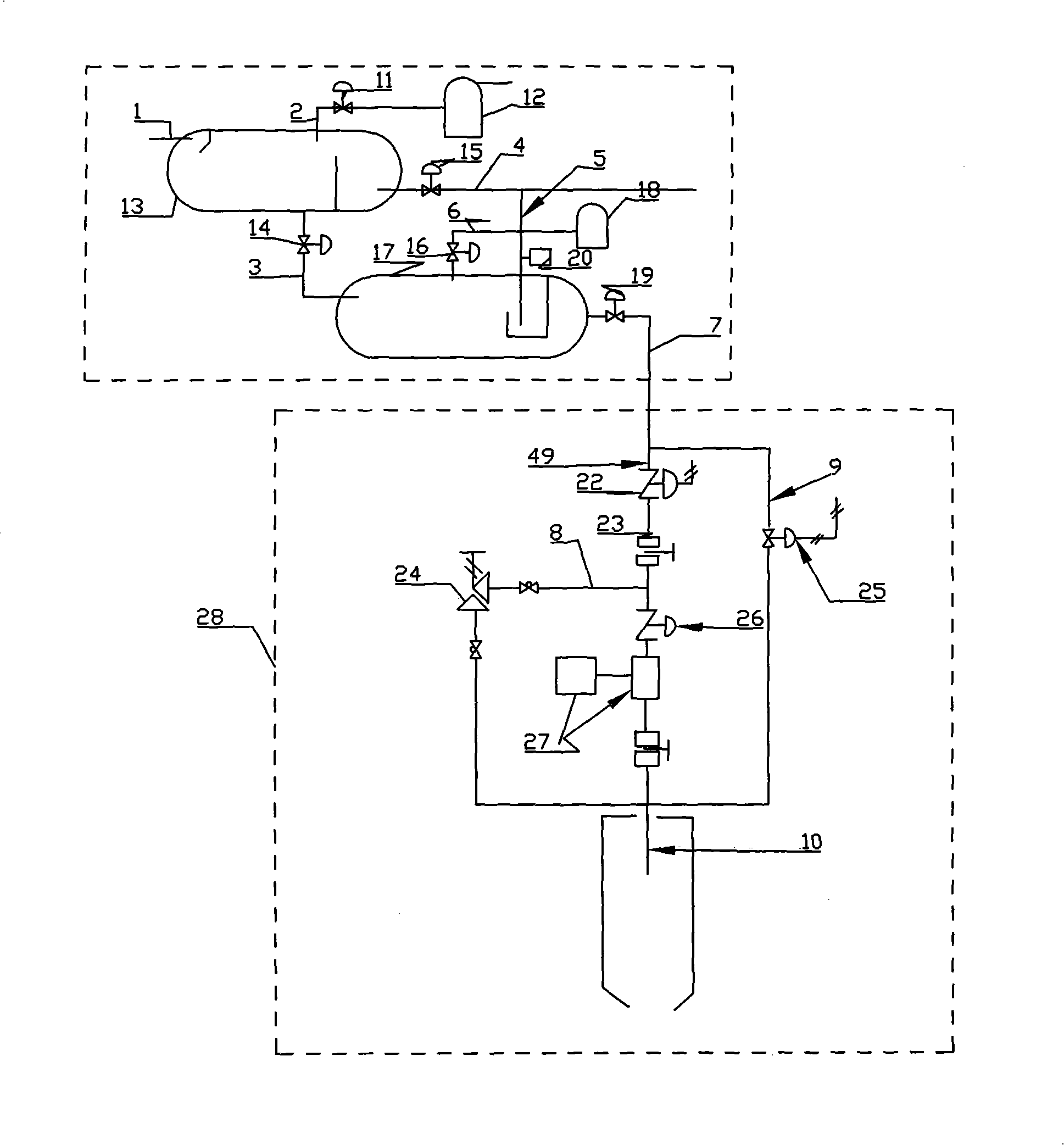
[0102] The present invention utilizes the above-mentioned existing power generation technology, and aims at the energy waste problem of the separator, and proposes a solution as follows: provide a water turbine and a steam turbine driven by the mechanical energy, heat energy and pressure energy of the water and gas processed by the oil-gas-water separator Method and device for comprehensive power generation by machine

Method used


Image

  • Method and device for utilizing flow separated from oil gas water separator for integral generation
  • Method and device for utilizing flow separated from oil gas water separator for integral generation
  • Method and device for utilizing flow separated from oil gas water separator for integral generation

Examples


Embodiment Construction

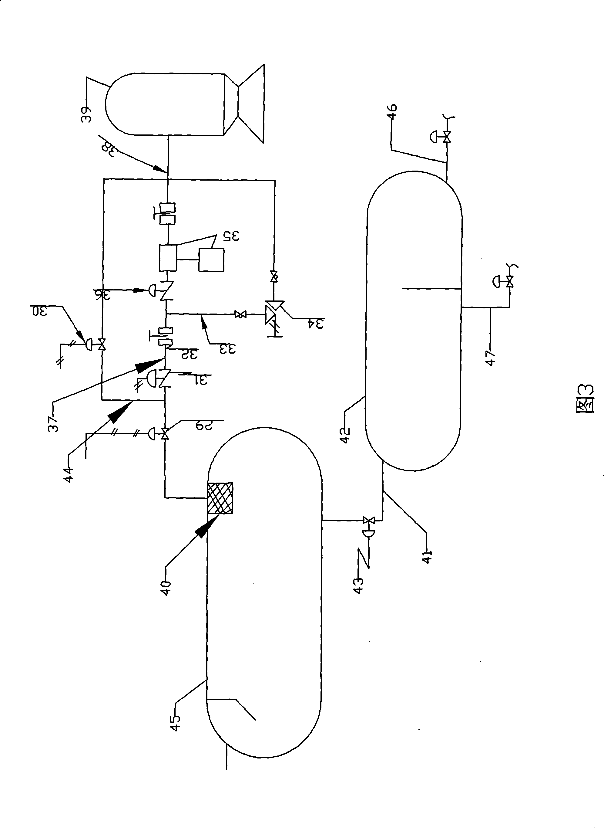
[0139] refer to Figure 1 to Figure 4 , the present invention is implemented like this:

[0140] The components of the method for generating electricity by using the excess pressure, excess energy and waste heat at the outlet of the oil-gas-water separator in the present invention include: an oil-gas-water primary separator and an oil-gas-water secondary separator, a water outlet pipeline, an oil outlet pipeline, an exhaust pipeline, an oil outlet pressure control valve, Water outlet control valve, gas outlet control valve, hydroelectric generator, pressure safety valve, bypass pipeline, geothermal power generation unit including: steam generator, steam turbine, condenser, circulation pump, geothermal generator.

[0141] Fig. 2 is a schematic diagram of the process flow of generating electricity from the outlet water of the separator of the present invention. The principle of implementing the method of the present invention is: the oil-gas-water mixture produced in the format...


PUM


Abstract

The invention relates to a comprehensive power generation method and a device thereof, which uses high-pressure high thermal energy fluid separated by an oil-gas-water separator, and adopts the method that the water processed by the oil-gas-water separator is discharged from a water outlet pipeline, and then enters a hydroelectric generator unit and / or a geothermal water power generation unit, wherein, the hydroelectric generator unit uses pressure energy and mechanical energy for producing water to drive a generator to generate power and uses geothermal energy of the produced water from separation to drive a steam turbine to generate power, and uses terrestrial heat for heating, thereby realizing the comprehensive, high-efficient and cascade utilization of the energy of the strata output; the gas processed by the oil-gas-water separator enters a turbine power generation unit via a natural gas outlet pipeline and is used for driving the steam turbine to generate power. The method has the beneficial effects that the pressure energy, thermal energy and gravitational potential energy of the water and the gas processed by the oil-gas-water separator are comprehensively used for pushing an impeller of a prime motor to rotate and driving the generator to generate power, thus realizing the purpose of using the residual energy and pressure producing the discharged water and gas for pushing the water turbine or a gas turbine to generate power, realizing the utilization of the residual energy and pressure, providing clean and unpolluted power source for oil fields, reducing the consumption of fossil energy, and realizing energy conservation and emission reduction.

Description

technical field [0001] The present invention relates to the oil-gas-water separation of oilfield separators and the use of high-pressure fluid at the separation outlet to drive generators to generate electricity, and in particular to the use of high-pressure, high-heat energy water and high-pressure gas separated by separators to use their mechanical energy, thermal energy and pressure energy to drive A method and device for integrated power generation by a water turbine and a steam turbine. Background technique [0002] Separator concept: The gravity oil-gas-water separator is a container that separates the three-phase mixture of oil, gas and water produced in the formation into oil, water and natural gas under the action of gravity differentiation, relying on the density difference between them. [0003] Separators also include various devices that rely on centrifugal force for separation, such as hydrocyclones, cyclone separators, etc., which are a type of cyclone separat...

Claims


Application Information

Patent Timeline
IPC IPC(8): F03B13/00F03B15/00F01D15/10F01D17/10E21B43/34
CPCY02E10/226Y02E10/20
Inventor 文立刚
Owner 文立刚
Learn More