Dual-purpose type padlock

A padlock, dual-use technology, applied in padlocks, combination locks, building locks, etc., can solve the problems of time-consuming, general products without suitable structure, and inconvenience.

Inactive Publication Date: 2008-09-17
JIN TAY IND CO LTD
View PDF0 Cites 3 Cited by
  • Summary
  • Abstract
  • Description
  • Claims
  • Application Information

AI Technical Summary

Problems solved by technology

[0003] Padlocks in the prior art are generally unlocked or locked by means of a key or a digital wheel. When locking, the key or the digital wheel must be operated in conjunction with the key while the lock is locked. action, so that the padlock of the prior art often spends more time in operation, and is very inconvenient
[0004] In order to solve the above-mentioned problems, the relevant manufacturers have tried their best to find a solution, but no suitable design has been developed for a long time, and the general products do not have a suitable structure to solve the above-mentioned problems. This is obviously the relevant industry. Urgent problem

Method used


Image

  • Dual-purpose type padlock
  • Dual-purpose type padlock
  • Dual-purpose type padlock

Examples


Embodiment Construction

[0087] In order to further explain the technical means and effects that the present invention adopts for reaching the intended invention purpose, the specific implementation, structure, characteristics and effects of the dual-purpose padlock proposed according to the present invention will be described below in conjunction with the accompanying drawings and preferred embodiments. , as detailed below.

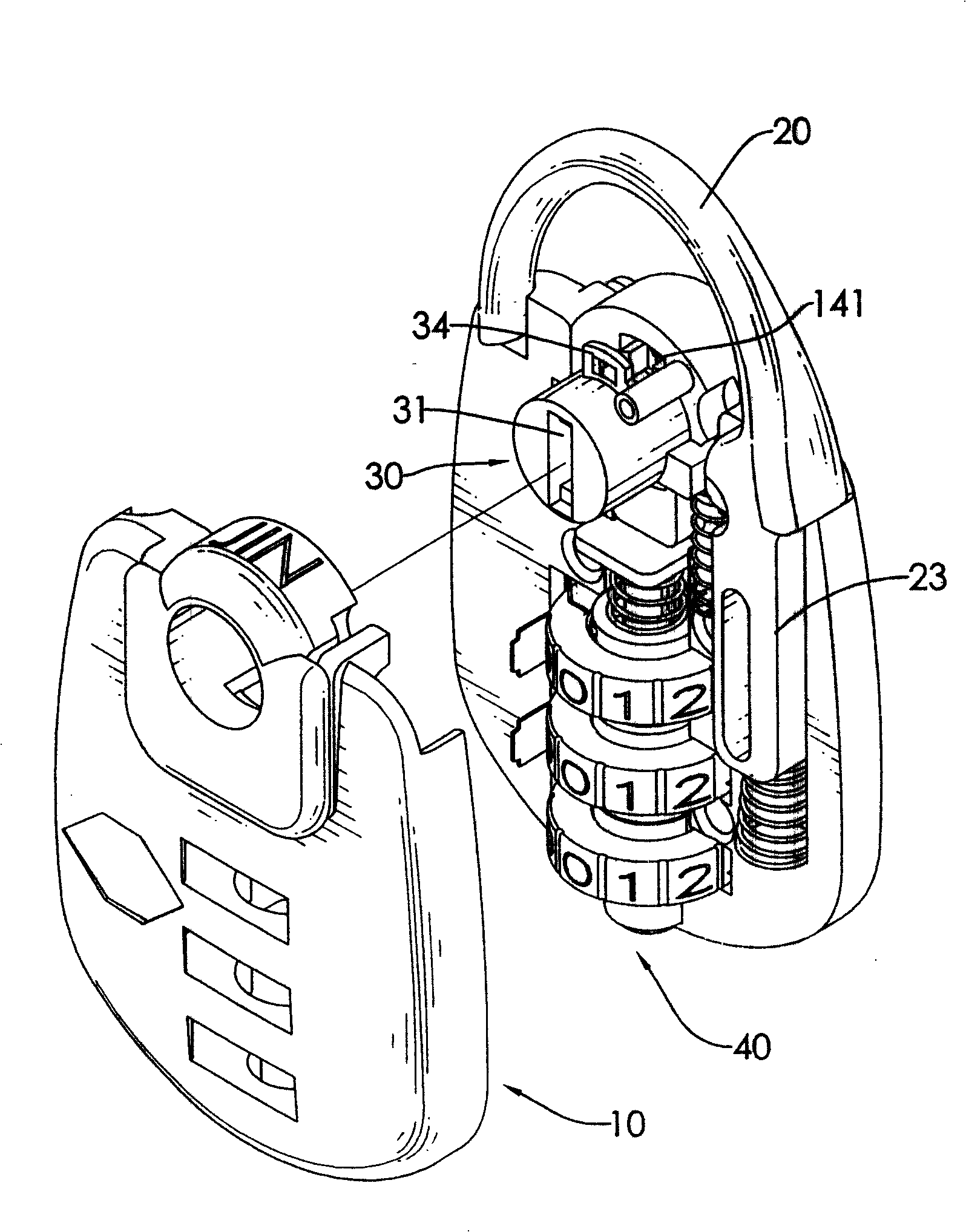
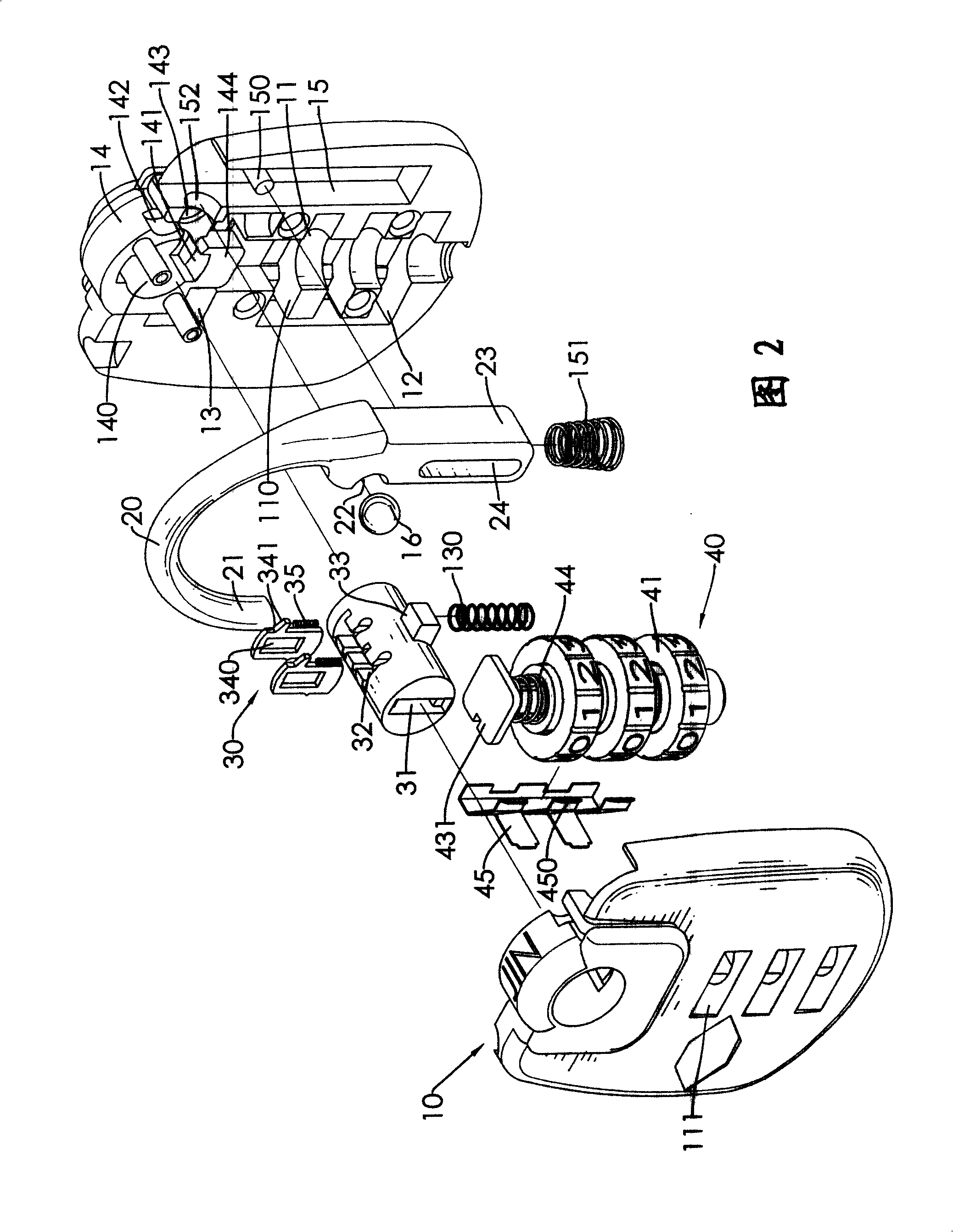
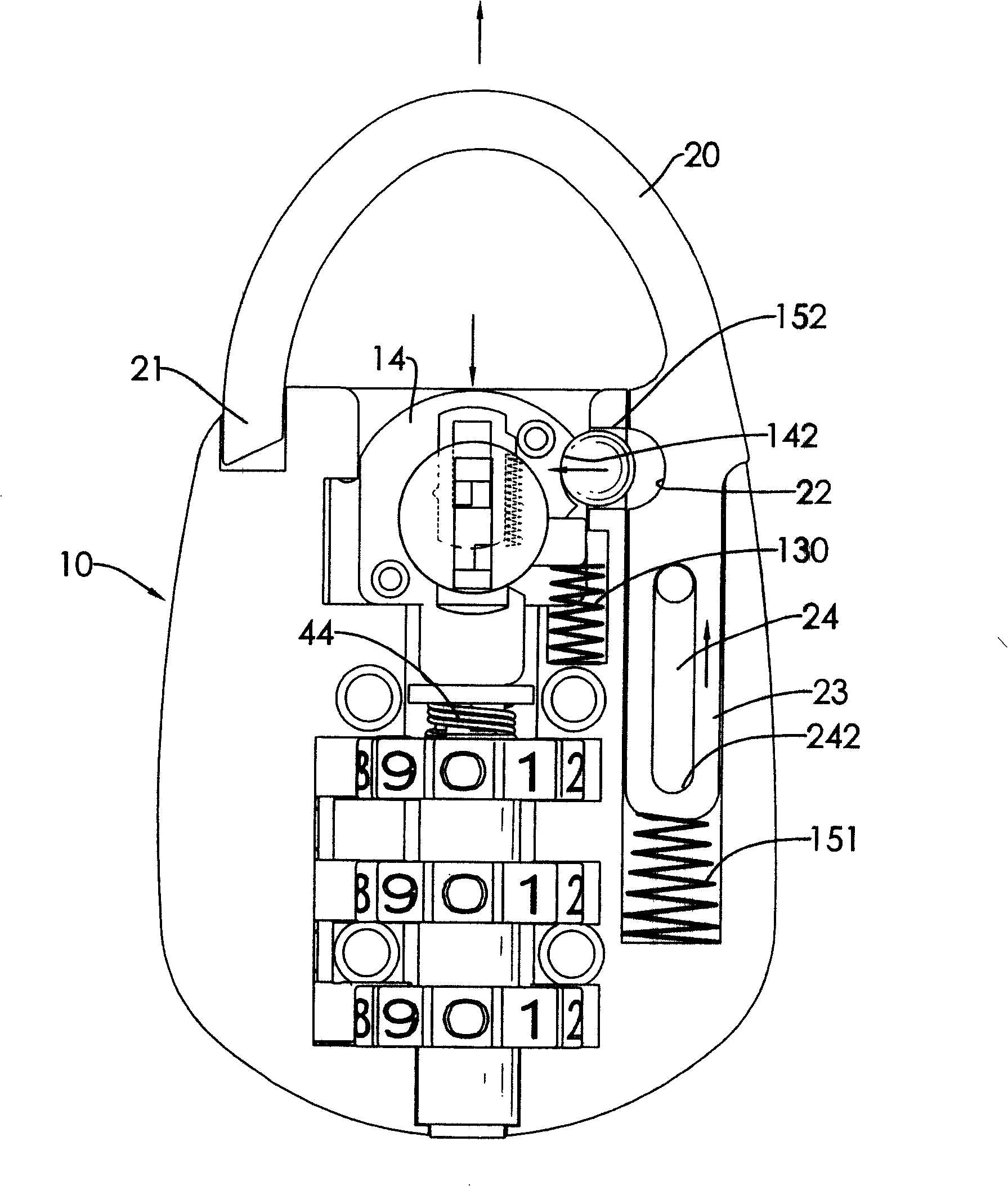
[0088] see figure 1 , Figure 2 and image 3 As shown, the dual-purpose padlock of the present invention includes a housing 10, a lock bolt 20, a lock cylinder portion 30 and a wheel set 40, wherein:

[0089] The casing 10 is composed of two halves that can be joined to each other, and a first chamber 11, a second chamber 12 and a third chamber 13 that communicate with each other are formed inside, wherein the first chamber 11 is formed with A plurality of wheel grooves 110 are parallel to each other, and the casing 10 is formed with windows 111 communicating with each wheel gr...


PUM


Abstract

The invention relates to a dual-purpose padlock. A lock plunger matches with a ball and other internal components for actuating, an external part is protruded to form a gap, thereby achieving unlocking in a manner of inputting a password or using a key according to the requirement of a user, i.e., the key is used to directly rotate a lock core to enable the lock plunger to be automatically ejected, thereby achieving the purpose of unlocking. The user can only apply force to press the lock plunger into the housing so as to enable the ball to be fixedly embeded on the lock plunger and enable the lock plunger to lock up, thereby achieving locking. The padlock is direct, quick and more convenient to use.

Description

technical field [0001] The invention relates to a lock, in particular to a dual-purpose padlock which has the function of unlocking with a key and a password, can be locked directly and quickly, and is more convenient to use. Background technique [0002] A padlock is a lock that can be applied to objects such as doors and storage boxes. It has a lock bolt that can be separated from the padlock body and fixed with the padlock when in use, so as to achieve various locking functions. [0003] Padlocks in the prior art are generally unlocked or locked by means of a key or a digital wheel. When locking, the key or the digital wheel must be operated in conjunction with the key while the lock is locked. action, so that the padlock of the prior art often spends more time in operation, and is very inconvenient. [0004] In order to solve the above-mentioned problems, the relevant manufacturers have tried their best to find a solution, but no suitable design has been developed for a...

Claims


Application Information

Patent Timeline
IPC IPC(8): E05B67/00E05B37/02
Inventor 苗新威
Owner JIN TAY IND CO LTD
Why Eureka
Try Eureka