Supercharge Your Innovation With Domain-Expert AI Agents!
Little water inversion-resistant toilet
Inactive Publication Date: 2010-12-22
陈云河
View PDF10 Cites 0 Cited by
Summary
Abstract
Description
Claims
Application Information
AI Technical Summary
This helps you quickly interpret patents by identifying the three key elements:
Problems solved by technology
Method used
Benefits of technology
Problems solved by technology
[0003] In order to overcome the deficiencies of the existing micro-water and non-reverse toilet controllers, such as relatively complex structure, high dimensional accuracy requirements for parts, relatively low dilution rate, easy oxidation of the surface of magnetic parts, and relatively low long-term operation quality, etc.
Method used
Image
Click on the blue label to locate the original text in one second.
Reading with bidirectional positioning of images and text.
Examples
Embodiment Construction
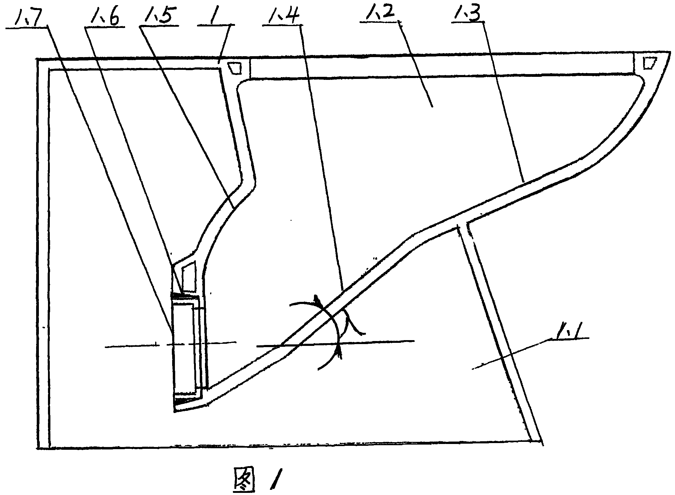
[0015] figure 1 As shown, the base 1.1 of the toilet shell 1 is integrated with the bedpan 1.2, the flat slope area 1.3, the steep slope area 1.4, the reflective surface 1.5, and the discharge port 1.6 of the bedpan 1.2 are integrated; the transition ring 1.7 is sealed and fixed in the discharge port 1.6 , the angle between the steep slope area 1.4 and the horizontal plane is λ.
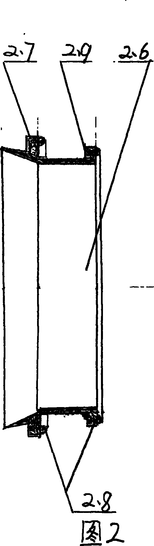
[0016] figure 2 As shown, the outer side of the closed end of the airtight ring 2.6 is shaped on a reseal ring 2.7, and the airtight side of the resealed ring 2.7 is shaped on a linear airtight ring 2.8, and the fixed end of the airtight ring 2.6 is shaped on an annular boss 2.9, and the front end of the annular boss 2.9 Made with a linear closed loop 2.8.
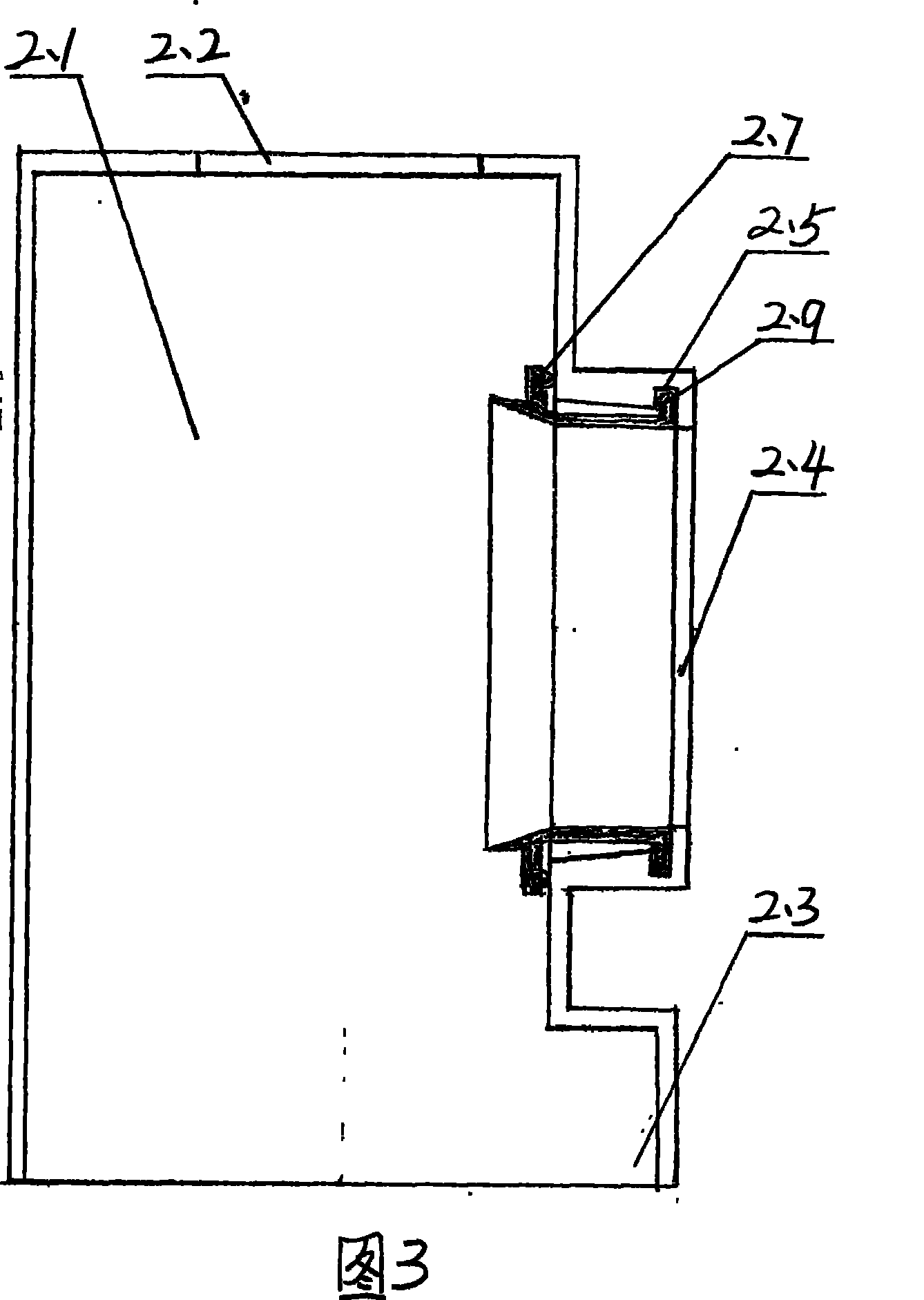
[0017] image 3 As shown, the top of the shell 2.1 has an assembly plate opening 2.2, the bottom is formed with a pipe joint 2.3, the middle part of the side wall is formed with a docking port 2.4, and the front end of the docking port 2.4 is...
PUM
Abstract
A trace water / non-return toilet bowl is composed of a toilet bowl shell and a controller. The toilet bowl preserves the structure of accumulation releasing in the forward direction and blocking in the opposite direction of the prior trace water / non-return toilet bowl, and adds an anti-splashing structure formed by a steep slope region and a reflector surface, a radial displacement space provided on the sealing end of a sealing ring and a structure of changing the sealing ring without detaching a controller, an anti-oxidation measure of a magnetic component surface, a structure of prolonging the opening time of a platform-shaped block and a structure of adjusting the changed moment of a middle wane after a long-term operation.
Description
Technical field [0001] The invention relates to a water-saving toilet with anti-reverse function. Background technique [0002] At present, the structure of the known micro-water non-return closet is made up of a bedpan, a controller storehouse, a base, and a controller. The bedpan, the controller storehouse and the base are made into one body, and the bedpan is made up of a discharge opening, a steep slope area, and a flat slope area. The controller is composed of a shell, an assembly plate, a ball crown plug, a seesaw, a weight ball, a weight ball bin, a magnet bin, shrapnel, a permanent magnet, an adjustment piece, an iron magnet, a shaft, a sealing ring, and a sealing chamber. The top of the housing is formed with a butt joint, the bottom is formed with a pipe joint, and the upper part of the side wall is provided with an assembly plate opening. A shaft hole is formed in the middle of the seesaw, a magnetic pole hole is formed at one end, and a spherical crown plug is ...
Claims
Application Information
Patent Timeline
Application Date:The date an application was filed.
Publication Date:The date a patent or application was officially published.
First Publication Date:The earliest publication date of a patent with the same application number.
Issue Date:Publication date of the patent grant document.
PCT Entry Date:The Entry date of PCT National Phase.
Estimated Expiry Date:The statutory expiry date of a patent right according to the Patent Law, and it is the longest term of protection that the patent right can achieve without the termination of the patent right due to other reasons(Term extension factor has been taken into account ).
Invalid Date:Actual expiry date is based on effective date or publication date of legal transaction data of invalid patent.
