
Method for detecting DC motor rotor location of no location sensor brushless

A technology of brush DC motor and rotor position, which is applied in the direction of electronically commutated motor control, electrical components, electronic commutator, etc., can solve the problems of detecting inductance and increasing the difficulty of realization, etc., and achieves the effect of easy realization and simple implementation

Inactive Publication Date: 2008-09-10
重庆百转电动汽车电控系统有限责任公司
View PDF2 Cites 45 Cited by
  • Summary
  • Abstract
  • Description
  • Claims
  • Application Information

AI Technical Summary

Problems solved by technology

[0005] The inductance measurement method judges the position of the rotor by detecting the change of the winding inductance of the permanent magnet synchronous motor. It is only related to the parameters of the motor and has nothing to do with the speed of the motor. It can also work when the speed of the motor is very low, but this method has shortcomings. The disadvantage is that it is difficult to detect the size of the inductance online in real time, which increases the difficulty of implementation

Method used


Image

  • Method for detecting DC motor rotor location of no location sensor brushless
  • Method for detecting DC motor rotor location of no location sensor brushless
  • Method for detecting DC motor rotor location of no location sensor brushless

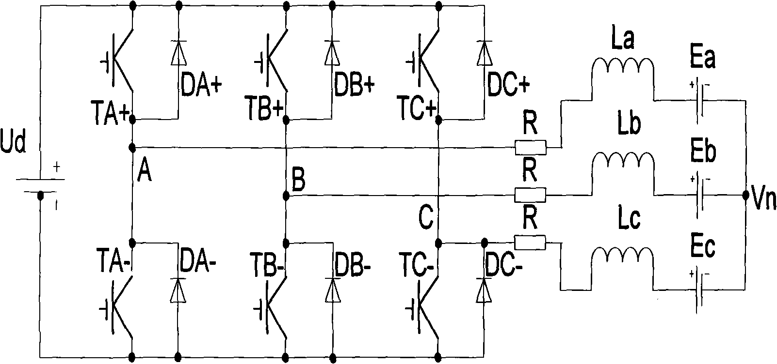
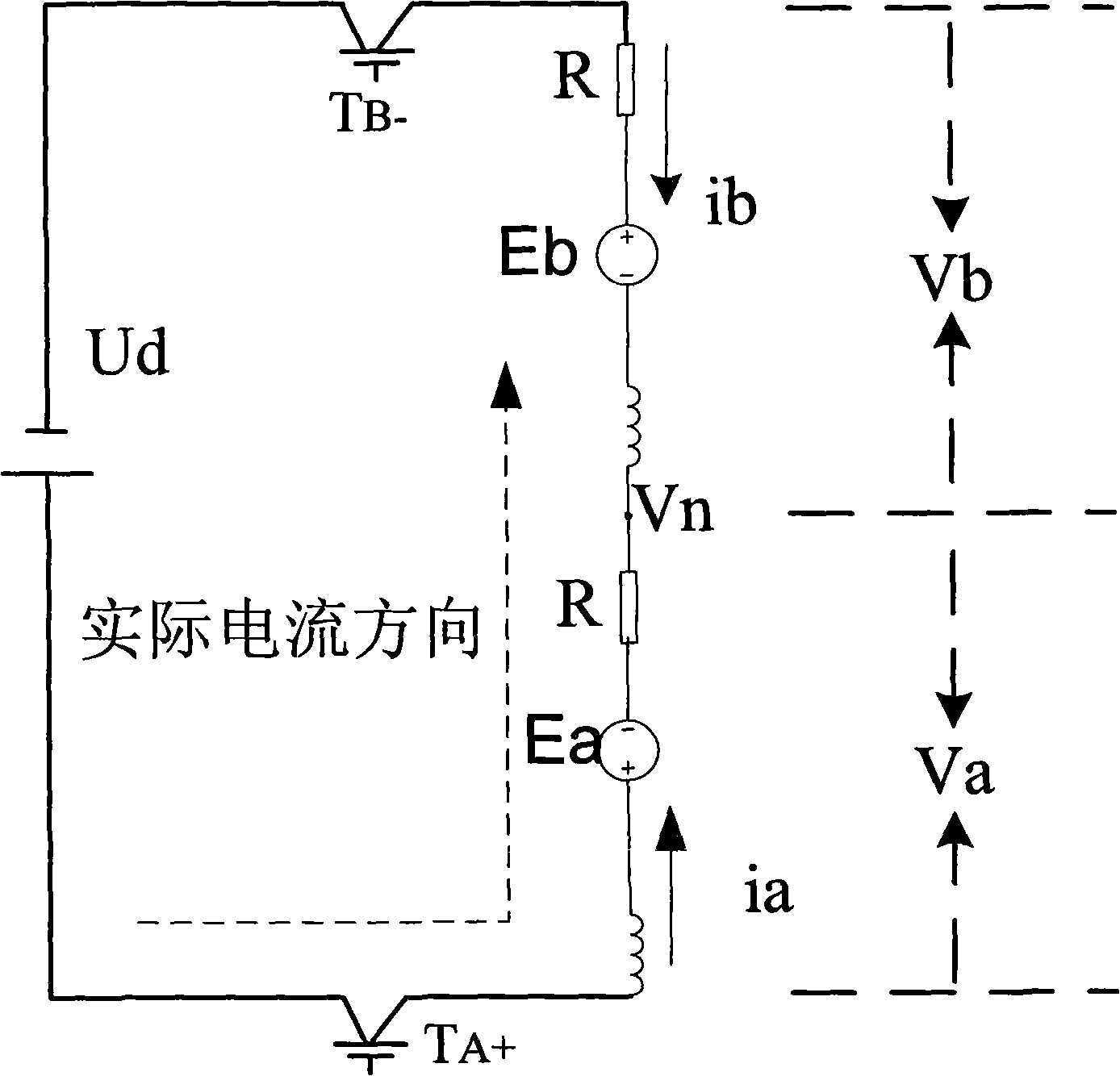
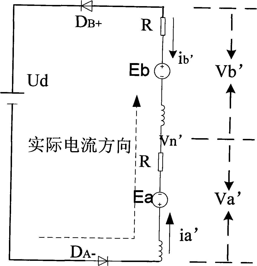
Examples


Embodiment Construction

[0023] The technical scheme of the present invention is described in detail below in conjunction with accompanying drawing and by specific embodiment:

[0024] In the salient pole permanent magnet brushless DC motor, the difference of d-axis and q-axis reluctance leads to the change of winding inductance. The q-axis inductance is not equal to the d-axis inductance, because the magnetic flux passing through the d-axis magnetic circuit passes through two permanent magnets, while the q-axis magnetic flux only passes through the air gap and the stator and rotor cores, not through the permanent magnets, so q The ratio of the shaft inductance to the d-axis inductance is much larger than that of the hidden pole motor, and the change of the inductance can be used as a function of the position to obtain the position information of the rotor. The inductance of each phase winding of a salient pole motor varies with the position of the rotor. In a two-pole motor, the inductances of stator...


PUM


Abstract

The invention discloses a method for detecting the position of a rotor of a brushless DC motor of a sensor without position by using the neutral point voltage. The structure of a rotor of the brushless DC motor takes the shape of a projecting pole, namely, the inductance Xd on a d axis of the rotor of the motor is not equal to the inductance Xq on a q axis of the motor. By detecting the neutral point voltage of a led-out winding of a stator of the brushless DC motor, the method of the invention can calculate the position of the rotor of the brushless DC motor with an energization mode each other, and the commutating time can be determined by lagging an electrical angle of 30 degrees. The method of the invention has the advantage of simple implementation of a back-electromotive force and is characterized in that the method takes no account of the motor revolution of an inductance method and can better determine the position of the rotor when the rotor revolution is close to from zero to the high speed as well as reliably and accurately commutate.

Description

technical field [0001] The invention relates to a method for detecting the rotor position of a brushless direct current motor by using a neutral point voltage, in particular to a method for detecting the rotor position of a brushless direct current motor without a position sensor. Background technique [0002] The position sensorless control of brushless DC motor (BLDC) does not need to install sensors, and has a wide range of applications. Compared with the position sensor method, it has great advantages. Therefore, the position sensorless control of brushless DC motors has become a research topic in recent years. hotspot. The key to position sensorless control is the rotor position signal detection method. [0003] The back EMF method and its improved algorithm are the most widely used techniques in rotor position signal detection methods at home and abroad. The principle of the back EMF method and its improved algorithm is to judge several special positions of the rotor...

Claims


Application Information

Patent Timeline
IPC IPC(8): H02P6/18H02P6/182
Inventor 王华斌刘和平付强王贵刘平王强高尚勇余银辉伍元彪
Owner 重庆百转电动汽车电控系统有限责任公司
Learn More