
Binding fastener

The technology of a fastener and a parent part is applied in the field of binding fasteners, which can solve the problems of difficulty in adjusting the height and angle of the fixed object, occupying the space used by pedestrians and non-motor vehicles, and affecting the safety of pedestrians and non-motor vehicles crossing the street. To achieve the effect of saving installation time and procedures, reducing installation costs, and reliable function

Inactive Publication Date: 2008-09-10
SOUTHEAST UNIV
View PDF0 Cites 2 Cited by
  • Summary
  • Abstract
  • Description
  • Claims
  • Application Information

AI Technical Summary

Problems solved by technology

[0002] At present, iron wires or bolts are used to fix objects on cylindrical rods, which is cumbersome and difficult to fix and disassemble. There are certain requirements for the shape of the rod, and it is not easy to adjust the height and angle of the fixed object.
After being exposed to wind and sun, it is easy to embroider and corrode, which reduces its service life and increases maintenance costs
Once disassembled, it becomes waste and cannot be reused
Secondly, in the field of transportation, due to the different shapes of the signs of various transportation facilities, the shape of the connectors when connecting these objects to the cylindrical rods will be complicated, and it is not convenient to fix various objects on the same cylindrical rod at the same time. Therefore, street lamps, traffic lights, traffic signs and other traffic facilities are respectively fixed on different poles, causing many poles to be erected on the side of the road, hindering people's sight and occupying the space for pedestrians and non-motorized vehicles , which affects the safety of pedestrians and non-motor vehicles crossing the street, especially poses a hidden danger to the traffic safety of the disabled

Method used


Image

  • Binding fastener
  • Binding fastener
  • Binding fastener

Examples


Embodiment Construction

[0017] Below in conjunction with accompanying drawing, the present invention is described in detail:

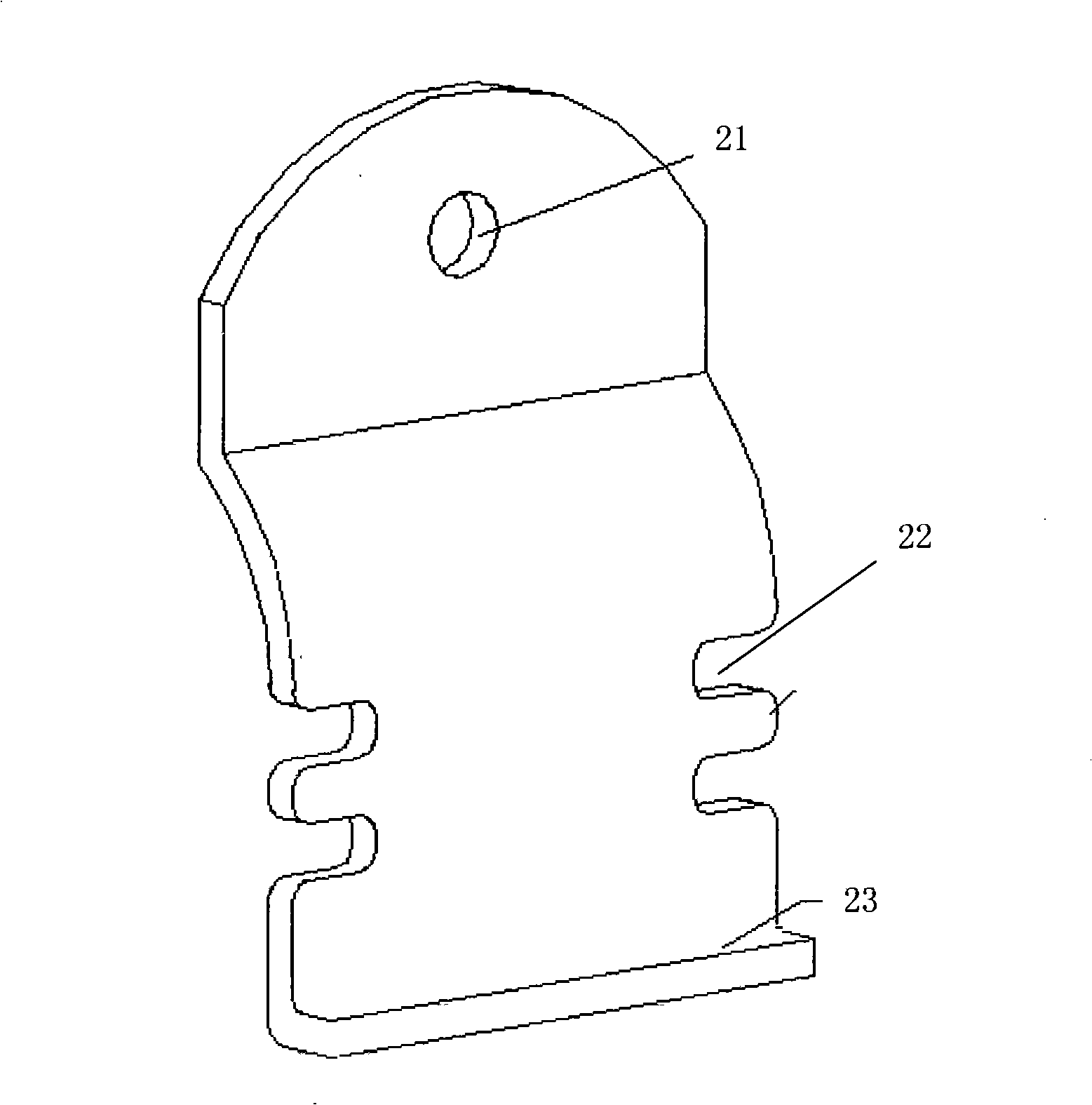
[0018] Refer to the drawings in the manual Figure 1 to Figure 3 , the binding fastener of the present invention includes a female part 1, the lower end of the female part 1 is a two separate bases 11 for connecting the first part 10, and the middle part of the female part 1 extends upwards from the two separate bases 11 The two extended side walls 12 have a junction 13 at the upper end of the parent part 1 for connecting the second component 10 ′, and the two ends of the junction 13 are transitionally connected with the upper ends of the two side walls 12 . Two clips 2 are detachably connected to the part 13, and the joint part (13) of the two clips 2 and the parent part can form a fastening space 4 for fixing the second part 10'.

[0019] A longitudinal opening 131 is arranged on the joint part 13, and the longitudinal opening 131 extends downward from the joint part 13 to...


PUM


Abstract

The invention discloses a binding fastener, which is used for forming a connection structure to fix a first connection part on a second connection part. The binding fastener comprises a parent item, the lower end of the parent item is provided with two separating bases which are used for connecting the first part, the middle part of the parent item is provided with two side walls which are extended upward along two separating bases, the upper end of the parent item is provided with a joint part which is used for connecting the second part, two ends of the joint part are connected transitionally with the upper ends of the two side walls, the joint part is detachably connected with two clamping pieces, the joint part of the two clamping pieces and the parent item can form a fastening space. Comparing with the prior art, the binding fastener adopts the parent item and two clamping pieces which are processed independently, the clamping pieces and the parent item are detachably connected so that the first connection part and the second connection part can be fixed simply and firmly, at the same time, the binding fastener has the advantages of easy disassembly, excellent universality, simplified and unified installment, large scale production and applicable to the actual project, low installation cost and low maintaining costs.

Description

technical field [0001] The invention relates to a fixing piece used for connecting different connecting parts, in particular to a binding fastener for fixedly connecting two kinds of connecting parts. Background technique [0002] At present, iron wires or bolts are used to fix objects on cylindrical rods, which is cumbersome and difficult to fix and disassemble. There are certain requirements for the shape of the rods, and it is not easy to adjust the height and angle of the fixed objects. After being exposed to wind and sun, it is easy to embroider and corrode, which reduces its service life and increases maintenance costs. After being disassembled, it becomes waste and cannot be reused. Secondly, in the field of transportation, due to the different shapes of the signs of various transportation facilities, the shape of the connectors when connecting these objects to the cylindrical rods will be complicated, and it is not convenient to fix various objects on the same cylin...

Claims


Application Information

Patent Timeline
IPC IPC(8): F16B1/00
Inventor 程琳孙宝
Owner SOUTHEAST UNIV
Learn More