
Broadcasting network, base station and broadcasting network blind zone positioning method

A broadcasting network and broadcasting base station technology, applied in the field of broadcasting technology, can solve the problems of high OPEX cost, occupying a lot of room space, unable to share public hardware parts and public network management with cellular base stations, achieve high transmission frequency accuracy, and reduce construction costs Effect

Active Publication Date: 2008-09-03
HUAWEI TECH CO LTD
View PDF0 Cites 16 Cited by
  • Summary
  • Abstract
  • Description
  • Claims
  • Application Information

AI Technical Summary

Problems solved by technology

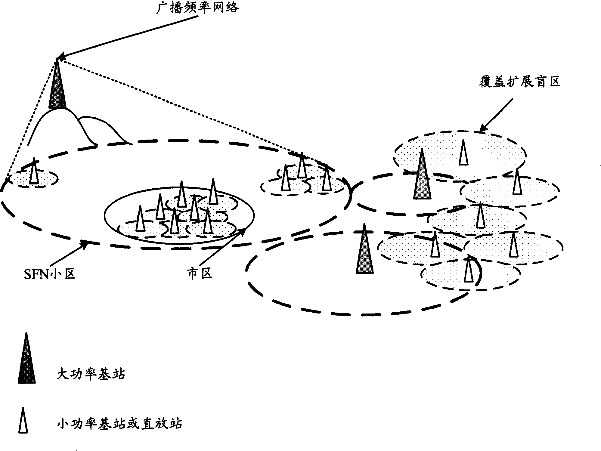
[0010] However, even so, the inventors of the present invention found that building a same-frequency / different-frequency broadcast repeater or a low-power broadcast base station still needs to occupy a lot of room space, and it is necessary to re-set up independent operation and maintenance units, transmission units, clock units, Main control unit, cabinet, antenna feeder, etc. cannot share common hardware and public network management with 3GPP / 3GPP2 / WiMAX cellular base stations, and CAPEX (investment cost) and OPEX (operating cost) are both high
[0011] In addition, in the process of building a blind-supplying network, how to obtain blind-spot information is also a concern of people. At present, there is no good way to automatically obtain blind-spot information, which makes the OPEX cost of building a blind-supplying network relatively high.

Method used


Image

  • Broadcasting network, base station and broadcasting network blind zone positioning method
  • Broadcasting network, base station and broadcasting network blind zone positioning method
  • Broadcasting network, base station and broadcasting network blind zone positioning method

Examples


Embodiment Construction

[0041] In order to make the purpose, technical solution and advantages of the present invention clearer, the following will further describe the implementation of the present invention in detail in conjunction with the accompanying drawings.

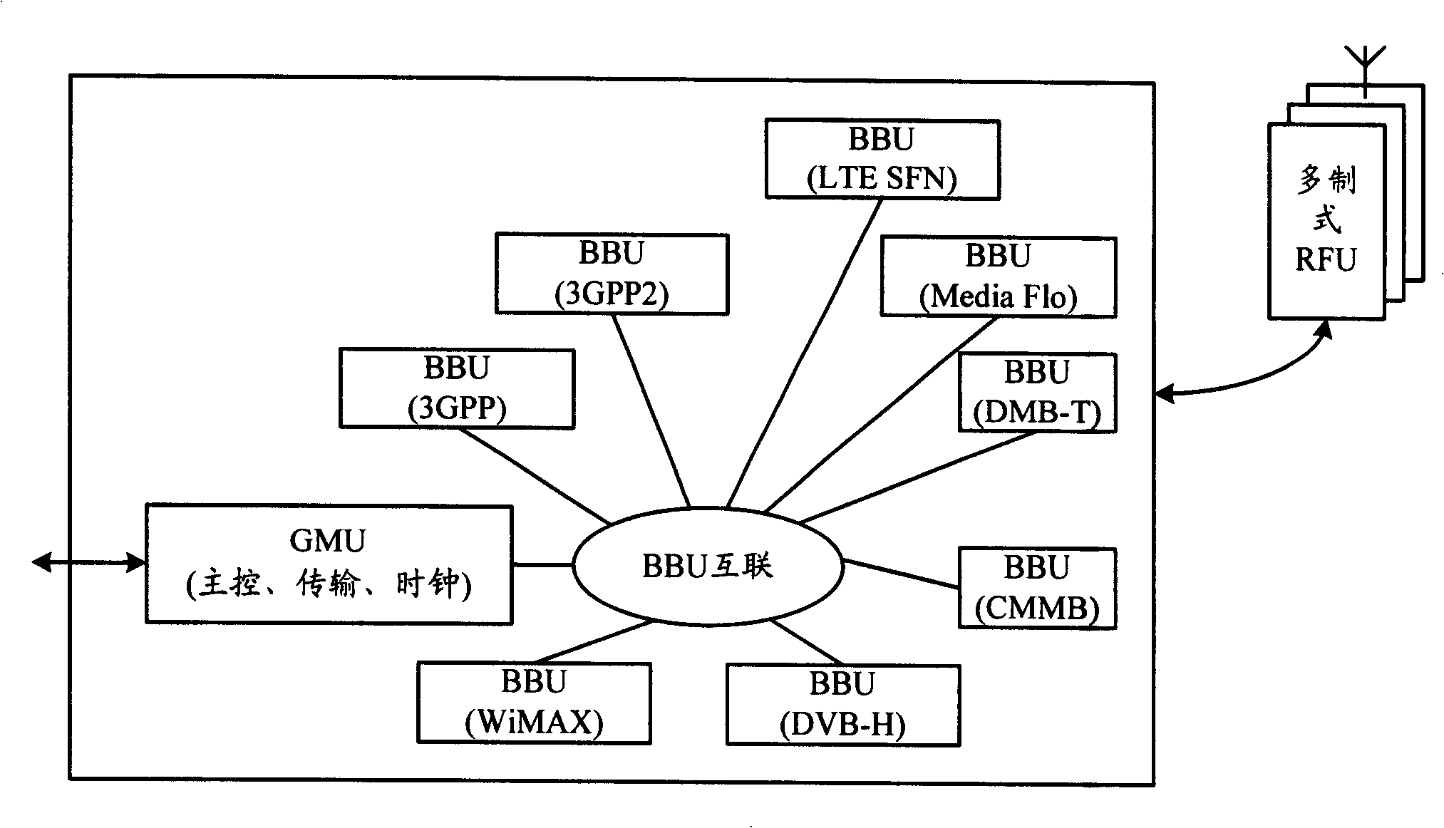
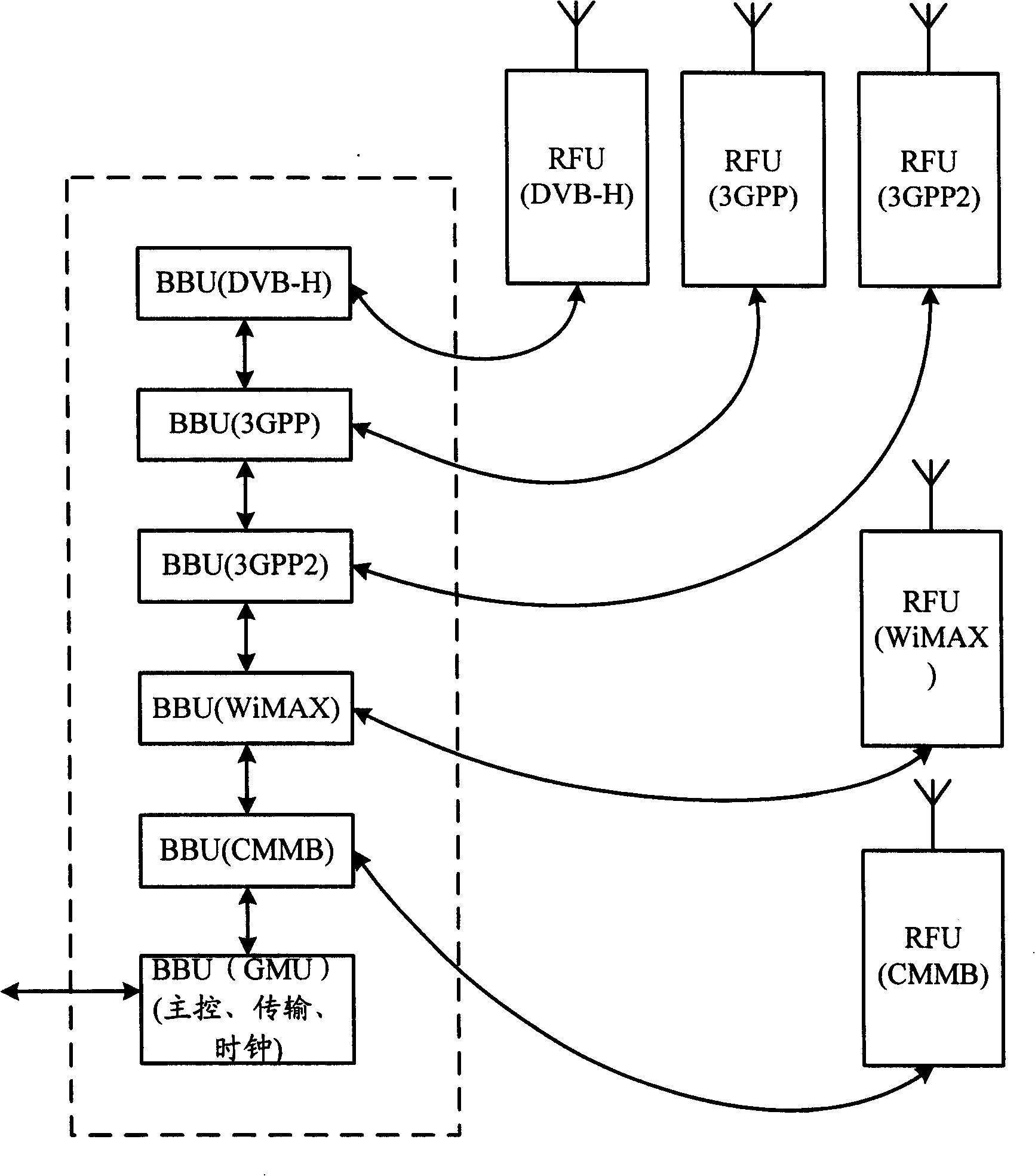
[0042] The first embodiment of the present invention relates to a broadcast network, including at least one high-power broadcast base station, and a low-power broadcast base station and a broadcast repeater used to fill in blind spots for the high-power broadcast base station, wherein the small power broadcast base station used to fill in blind The power broadcast base station or broadcast repeater shares a common module with base stations of other networks. The common module provides master control, transmission, and clock. From a functional point of view, the common module can be a general management unit (General Manage Unit, referred to as "GMU") ”), by sharing the GMU, the construction cost of the blind-filling network of the broadcast...


PUM


Abstract

The invention relates to wireless communication field, discloses a localization method for the broadcasting network, base station and broadcasting network blind zone. A low power broadcasting base station and / or a broadcasting repeater for blind complement shares one set of components with base stations of other network base station for providing a main control, transmission and clock, therefore reducing the construction cost of blind complement in the broadcasting network. The broadcasting repeater is made into the radio frequency unit form to share public modules of other network base station, and the remote repeater can be configured and controlled by the main control, transmission and clock provided by the public modules. A multi-module terminal measures the signal quality of the broadcasting network, submits the measuring result and the position information of the multi-module terminal when measuring to a function entity at the network side which determines the position of the blind zone based on the result and the position information, therefore locating the blind zone without increasing the maintenance cost.

Description

technical field [0001] The invention relates to the field of wireless communication, in particular to broadcasting technology. Background technique [0002] With the rapid popularization of mobile multimedia services and the development of digital TV technology and networks, mobile TV has gradually become a hot topic in China. Judging from the current application situation, the implementation methods of mobile TV can be mainly divided into the following types: The first is based on terrestrial broadcasting, including the European Digital Video Broadcasting-Handheld (Digital Video Broadcasting-Handheld, referred to as "DVB-H ") technology, South Korea's terrestrial digital multimedia broadcasting (Digital Multimedia Broadcasting-Terrestrial, referred to as "DMB-T") technology, and the Media FLO technology launched by Qualcomm (Qualcomm), etc.; Satellite Digital Multimedia Broadcasting (S-DMB for short) and China Mobile Multimedia Broadcasting (CMMB for short) technology; the...

Claims


Application Information

Patent Timeline
IPC IPC(8): H04B7/185H04B7/14H04Q7/30H04Q7/38H04Q7/34H04H20/74H04W4/06
CPCH04H20/06H04W4/06Y02D30/70
Inventor 赵其勇张运红赵宏宇
Owner HUAWEI TECH CO LTD
Learn More