Electric kitchen appliance with bayonet joints for electric motor and transmission stage and method for mounting an electric kitchen appliance

A kitchen equipment and bayonet joint technology is applied in the field of installing electric kitchen equipment, especially electric single-use or universal kitchen machines, electric single-use or universal kitchen machines, electric motors and a transmission stage, which can solve the problems of expensive installation and manufacturing, etc. To simplify installation, improve product flexibility, and secure connections

Active Publication Date: 2012-02-01
BSH BOSCH & SIEMENS HAUSGERAETE GMBH
View PDF1 Cites 0 Cited by
  • Summary
  • Abstract
  • Description
  • Claims
  • Application Information

AI Technical Summary

Problems solved by technology

The known kitchen appliances are therefore relatively expensive to install or manufacture

Method used


Image

  • Electric kitchen appliance with bayonet joints for electric motor and transmission stage and method for mounting an electric kitchen appliance
  • Electric kitchen appliance with bayonet joints for electric motor and transmission stage and method for mounting an electric kitchen appliance
  • Electric kitchen appliance with bayonet joints for electric motor and transmission stage and method for mounting an electric kitchen appliance

Examples


Embodiment Construction

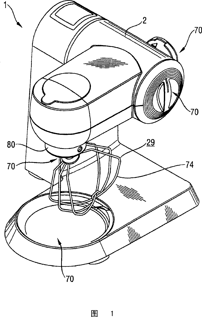
[0037] figure 1Shown is a perspective oblique view from the side of a kitchen appliance 1 according to the invention, which has a appliance housing 2 and four different sockets 70 for tools 29 which can be designed as whisks 74. Here, the motor 3 (see Figures 2 to 6 ) drives three of the four sockets 70.

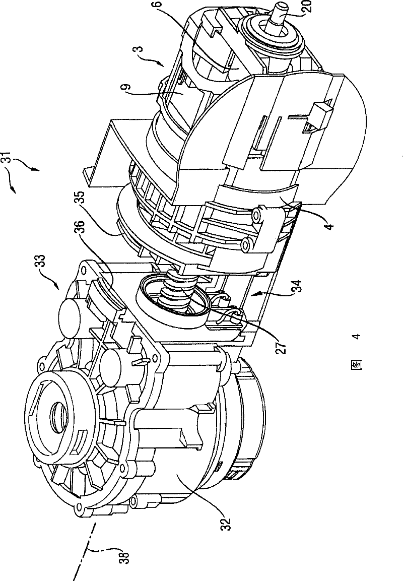
[0038] figure 2 Shows a perspective oblique view of the motor-transmission stage arrangement 31 of the kitchen appliance 1 according to the invention during pre-assembly, wherein the transmission stage 33 is connected to the electric motor 3 by connecting the transmission with a bayonet joint 34 The housing 32 and the motor housing 4 are connected to each other by sliding the transmission housing 32 onto the motor housing 4 , twisted at an angle, and securing it by rotation in the direction of rotation 47 . By means of the bayonet joint 34 , the transmission stage 33 can be connected easily but securely to the electric motor 3 by means of a swivel-extension movement. ...


PUM


Abstract

An electric motor-driven kitchen appliance includes an electric motor and a gear stage. The electric motor includes a motor housing and the gear stage includes a gear case. The motor housing and gear stage are connected to each other by a bayonet lock. The electric motor and the gear stage are provided with the respective bayonet lock parts designed for the kitchen appliance.

Description

technical field [0001] The invention relates to an electric kitchen appliance, in particular an electric single-use or universal kitchen machine having an electric motor and a transmission stage, wherein the electric motor has a motor housing and the transmission stage has a transmission housing; An electric motor and a transmission stage of said kitchen appliance; and the invention also relates to a method for installing an electric kitchen appliance, in particular an electric single-use or universal kitchen machine. Background technique [0002] DE 2551842 describes an electrically operated power unit for a kitchen machine with a planetary gear with bevel gear meshing, the planetary gears of which rotate in an inclined axis and in Its axis intersects the axis of the central gear around which the driven tool is moved by means of the planetary gear. [0003] The production of known kitchen appliances usually provides that the electric motor and the gear stage must be insert...

Claims


Application Information

Patent Timeline
Patent Type & Authority Patents(China)
IPC IPC(8): A47J43/08
CPCA47J43/08Y10T74/19828Y10T74/19565Y10T29/49002
Inventor P·科瓦奇克J·佩塞克
Owner BSH BOSCH & SIEMENS HAUSGERAETE GMBH
Why Eureka
Try Eureka