
Laser pen indication and luminescent spot track recognizing method

A recognition method and laser pointer technology, applied in character and pattern recognition, instruments, electrical digital data processing, etc., can solve problems such as the inability to achieve the accuracy of ordinary projection screens, the uncertainty of control objects, and difficult operations

Inactive Publication Date: 2008-08-27
SHANGHAI JIAO TONG UNIV
View PDF1 Cites 66 Cited by
  • Summary
  • Abstract
  • Description
  • Claims
  • Application Information

AI Technical Summary

Problems solved by technology

However, the target screen size of the applicable object of this method is limited, and the accuracy required by the ordinary projection screen size cannot be achieved. Due to the uncertainty of the control object, it lacks universal applicability. Due to the limitation of factors, the above-mentioned deficiencies will easily lead to difficulties in operation for users

Method used


Image

  • Laser pen indication and luminescent spot track recognizing method
  • Laser pen indication and luminescent spot track recognizing method

Examples


Embodiment Construction

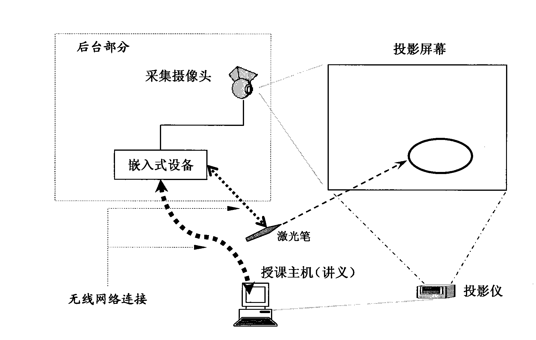
[0054] The embodiments of the present invention are described in detail below in conjunction with the accompanying drawings: this embodiment is implemented on the premise of the technical solution of the present invention, and detailed implementation methods and specific operating procedures are provided, but the protection scope of the present invention is not limited to the following the described embodiment.

[0055] This embodiment is used to identify the teacher's instructions on the display screen through a laser pointer.

[0056] like figure 1 As shown, this embodiment includes the following steps:

[0057] Step 1. The user indicates the position of the light spot on the display screen through the laser pen, and expresses the trajectory information such as graphics and text from the multiple light spot positions. The video input device obtains the video information of the target screen, and the collected video Information transmission to embedded devices;

[0058] Th...


PUM


Abstract

The present invention discloses a laser pen indicating and light spot trajectory identification method which belongs to the interactive reorganization technical field. Step 1, according to laser pen indicating information, a user obtains video information of a display screen from a video input device; step 2, an embedded device extracts light spots from the acquired video information, and determines the positions of the light spots after a de-noising process; step 3, the position coordinates of the light spots are transmitted to a computer which controls a target screen; step 4, according to the position coordinates of the light spots, the computer which controls the target screen recognizes the light spot trajectory; with the specific light spot information, the trajectory information indicated by the user is obtained; when the recognition is succeeded, step 5 is carried out; step 5, after the trajectory recognition is succeeded, the trajectory of the recognition result of the original trajectory is optimized, so that a new trajectory is obtained; the optimized result is displayed with visually optimized effect on the target screen to replace the indication effect of the step 3. The method can be applied in various interactive recognition display circumstances so as to carry out highly effective light spot analysis and trajectory recognition.

Description

technical field [0001] The invention relates to a method in the field of optoelectronic technology, in particular to a method for laser pointer indication and light spot track recognition. Background technique [0002] In recent years, with the continuous change of the teaching environment and the continuous expansion of the scale, the learning efficiency has been affected to a certain extent. Therefore, various technologies applied to the large-scale teaching environment have been proposed one after another. In terms of the display effect of the teaching screen, it is different from the physical equipment. Various improved intelligent technologies are also being widely used and applied to various interactive identification display environments. [0003] After searching the literature of the prior art, it was found that the Chinese patent application number 200710026848.1, the patent name is "Method for Replacing Button Input with Photoelectric Trajectory Input", the patent ...

Claims


Application Information

Patent Timeline
Patent Type & Authority Applications(China)
IPC IPC(8): G06F3/042G06K9/72G09B17/02
Inventor 陈刚鲁晨平申瑞民
Owner SHANGHAI JIAO TONG UNIV
Learn More