
Adjustable mainboard support in computer host box and method of use thereof

A motherboard bracket and computer mainframe technology, which is applied to the computer, computer motherboard installation method in the computer case, and the computer case field, can solve the problems of large volume, cumbersome installation and disassembly, and fighting, and achieve a large number of loads, various installation methods, The effect of great flexibility

Inactive Publication Date: 2008-08-27
北京瀚弘达科技有限公司
View PDF0 Cites 4 Cited by
  • Summary
  • Abstract
  • Description
  • Claims
  • Application Information

AI Technical Summary

Problems solved by technology

[0002] At present, the computer cases on the market generally have the following deficiencies, defects and drawbacks due to the irrationality in their structure: they are large in size and can only be installed with standard-sized motherboards, such as large ones with functions such as RAID. When the size of the motherboard is different, it will conflict with the optical drive, and even in some cases, the optical drive bracket will block the motherboard. On the inner panel of the case, its position cannot be adjusted after being fixed, so that at least dozens of screw mounting holes need to be provided on the bottom plate of the case to ensure the installation of civilian-grade motherboards; It is relatively long, and the distance between the edge of the main board and the optical drive tray should be kept at least 50mm. Only in this way can we ensure that the main board will not "fight" with the optical drive due to the size problem; moreover, the current installation method of the main board is not conducive to the heat dissipation on the back of the main board. It does not meet the requirements of energy saving and environmental protection, and requires special tools for installation and disassembly, and the overall production consumes a lot of raw materials
To sum up, the deficiencies, defects and disadvantages of the current existing technology are: the case is too bulky and unsuitable; , It is easy to cause conflicts between the motherboard and the installation of the CD-ROM and "fight", it is not conducive to the heat dissipation of the motherboard and lacks energy saving and environmental protection, the installation and disassembly are cumbersome and labor-intensive, and the production and use are cumbersome and the overall benefit is poor. Can not adapt to the fast and violent computer Development needs but lack of forward-looking...etc.

Method used


Image

  • Adjustable mainboard support in computer host box and method of use thereof
  • Adjustable mainboard support in computer host box and method of use thereof
  • Adjustable mainboard support in computer host box and method of use thereof

Examples


specific Embodiment approach 2

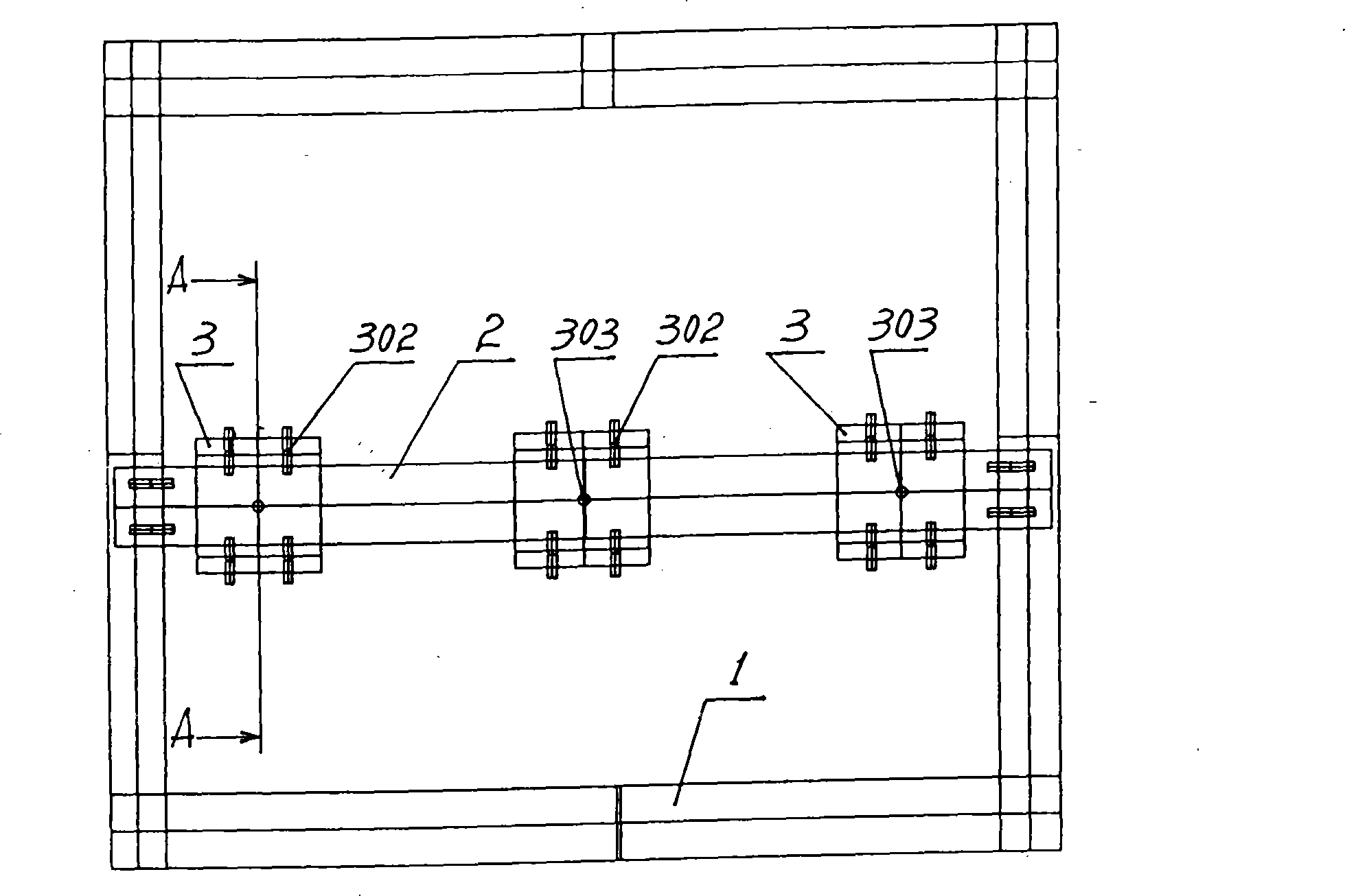
[0053] Carry out according to specific embodiment one, just guide rail and slide block are carried out according to Fig. 6, just as specification attached figure 1 , 2 , 3, 6 shown: Figure 6 is figure 1 The schematic diagram of the way from A-A to B in the middle; that is, the enlarged cross-sectional schematic diagram of the second structure mode of the guide rail and the slider in the specific embodiment of the present invention. This figure shows that the section of the guide rail is a trapezoidal convex track structure, the cross section of the slideway on the slider is in the shape of a trapezoidal groove slideway, and the condition that the guide rail and the slider are adapted to each other. Through the specific implementation of the second structure of the guide rail and the slider, the expected good results have been obtained after an assessment trial.

specific Embodiment approach 3

[0054] Carry out according to specific embodiment one, just guide rail and slide block are carried out according to Fig. 7, just as specification attached figure 1 , 2 , 3, 7 shown: Figure 7 is figure 1 The schematic diagram of the A-A to C mode in the middle; that is, the enlarged cross-sectional schematic diagram of the third structure mode of the guide rail and the slider in the specific embodiment of the present invention. This figure shows that the section of the guide rail is a square track structure, the cross section of the slideway on the slider is in the shape of a square hole slideway, and the situation that the guide rail and the slider are adapted to each other. Through the specific implementation of the third structure of the guide rail and the slider, the expected good results have been obtained after an assessment trial.

specific Embodiment approach 4

[0055] Carry out according to specific embodiment one, just guide rail and slide block are carried out according to Fig. 8, just as specification attached figure 1 , 2 , 3, 8, and 9: Figure 8 is figure 1 The schematic diagram of the way from A-A to D in the middle; that is, the enlarged cross-sectional schematic diagram of the fourth structure mode of the guide rail and the slider in the specific embodiment of the present invention. This figure shows that the section of the guide rail is a circular track structure, the cross section of the slideway on the slider is in the shape of a circular hole slideway, and the situation that the guide rail and the slider are adapted to each other. Figure 9 for figure 1 The enlarged cross-sectional schematic diagram of the slider in the A-A direction of D; that is, the enlarged cross-sectional schematic diagram of the fourth structural mode of the slider in the specific embodiment of the present invention. This figure shows that the cro...


PUM


Abstract

The present invention provides a computer host case inside adjustable mainboard bracket and a usage thereof, relating to the computer technical field. The computer host case inside adjustable mainboard bracket adopts a technical key of organically combining a bracket, a guide rail and a slider to provide a connection mode of a computer mainboard. The computer host case inside adjustable mainboard bracket has a computer host case fastened with the bracket, wherein the bracket is fastened with the guide rail; the guide rail is in slide movable connection with the slider and is fastened through a slider fixing screw hole on the slider; the slider and the computer mainboard are fastened through a mainboard fixing screw hole on the slider. The usage of the computer host case inside adjustable mainboard bracket comprises the following steps that: the computer host case inside adjustable mainboard bracket is fastened inside the computer host case; the guide rail and the slider are loosened so as to allow the slider to slide to a needed position; the computer mainboard is fastened on a mainboard fixing screw hole on the slider; the slider is fixed on the guide rail through the slider fixing screw hole of the slider. The computer host case inside adjustable mainboard bracket is used for the installation of the computer mainboard. The intrinsic structure of the case is adapted to various mainboards; after the mainboard is fixed, the mainboard can be adjusted at will and does not conflict with a CD driver, thereby adapting to the development needs of computers.

Description

technical field [0001] The present invention relates to the adjustable mainboard bracket inside the computer main box and the method of use thereof, and relates to the technical field of computers; in particular to the technical field of computer cases; especially to the technical field of installation methods for computer mainboards in the computer case; in particular to the adjustable mainboard bracket inside the computer main box and methods of use thereof. Background technique [0002] At present, the computer cases on the market generally have the following deficiencies, defects and drawbacks due to the irrationality in their structure: they are large in size and can only be installed with standard-sized motherboards, such as large ones with functions such as RAID. When the size of the motherboard is different, it will conflict with the optical drive, and even in some cases, the optical drive bracket will block the motherboard. On the inner panel of the case, its posit...

Claims


Application Information

Patent Timeline
Patent Type & Authority Applications(China)
IPC IPC(8): G06F1/18
Inventor 赵普刘金林刘杰
Owner 北京瀚弘达科技有限公司
Learn More