Yarn nozzle telescopic oscillating control mechanism for applique shuttle box

A telescopic control and yarn feeder technology, which is applied in textiles and papermaking, weft knitting, knitting, etc., can solve the problems of inconvenient installation of the return pressure spring, complex structure of the yarn feeder assembly, and increased production costs, etc., and achieves simple structure, Easy installation and debugging, not easy to distort

Inactive Publication Date: 2008-08-27
冯加林 +1
View PDF0 Cites 5 Cited by
  • Summary
  • Abstract
  • Description
  • Claims
  • Application Information

AI Technical Summary

Problems solved by technology

[0006] The yarn feeder telescopic swing control mechanism of the above-mentioned intarsia shuttle box has the following deficiencies: First, the structure of the yarn feeder assembly is relatively complicated, which increases the production and installation work. cost
Third, the in

Method used


Image

  • Yarn nozzle telescopic oscillating control mechanism for applique shuttle box
  • Yarn nozzle telescopic oscillating control mechanism for applique shuttle box
  • Yarn nozzle telescopic oscillating control mechanism for applique shuttle box

Examples


Embodiment Construction

[0018] The present invention will be further described below in conjunction with embodiment.

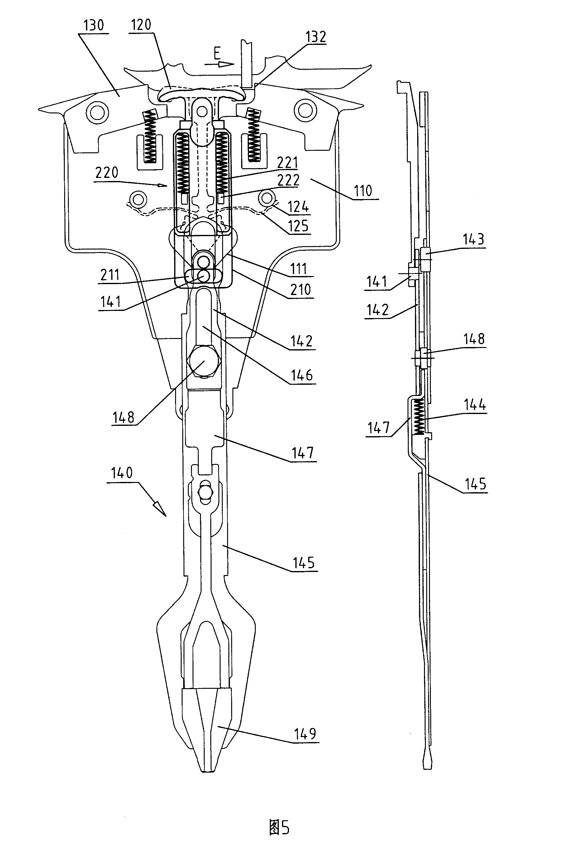
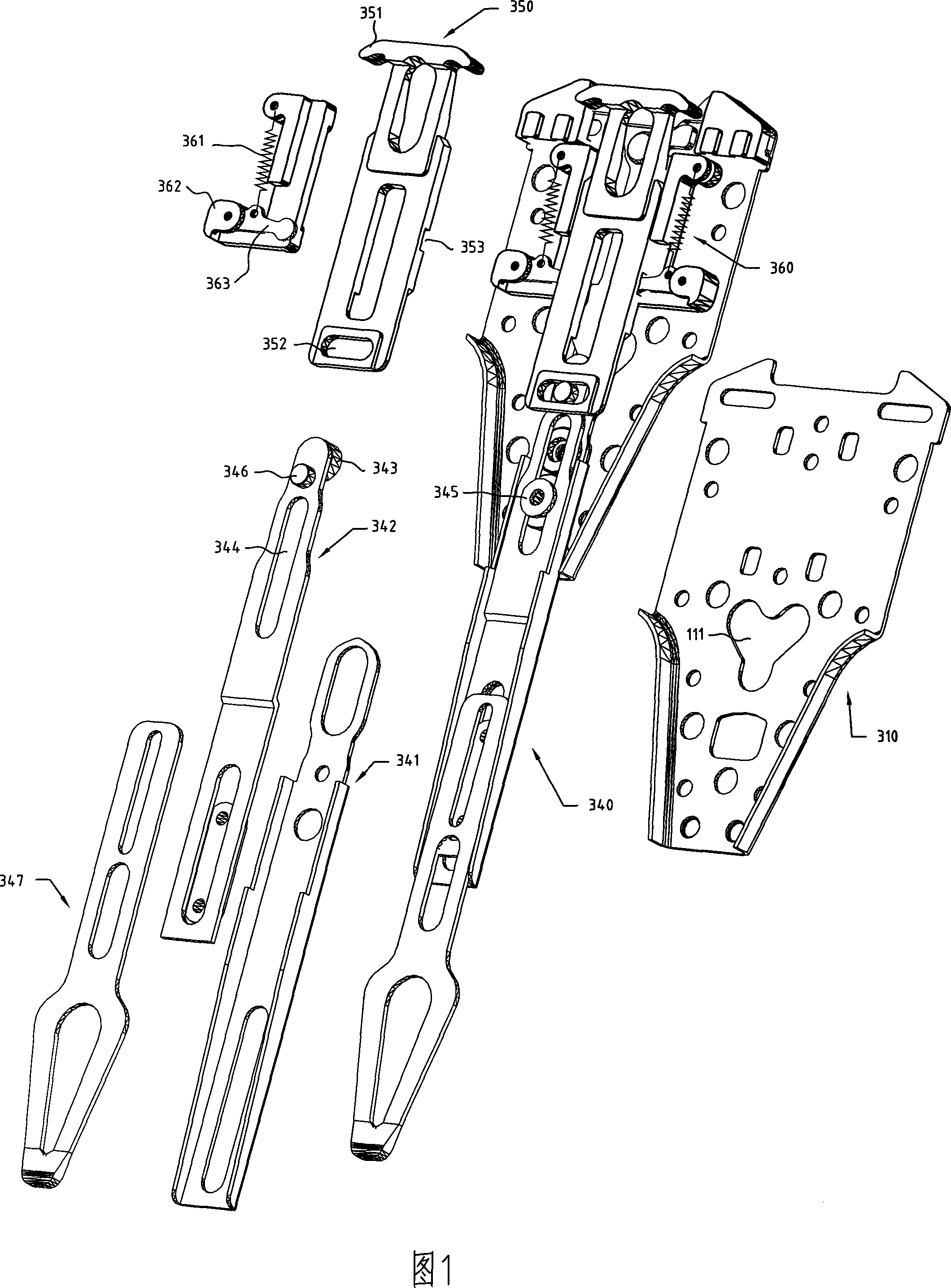
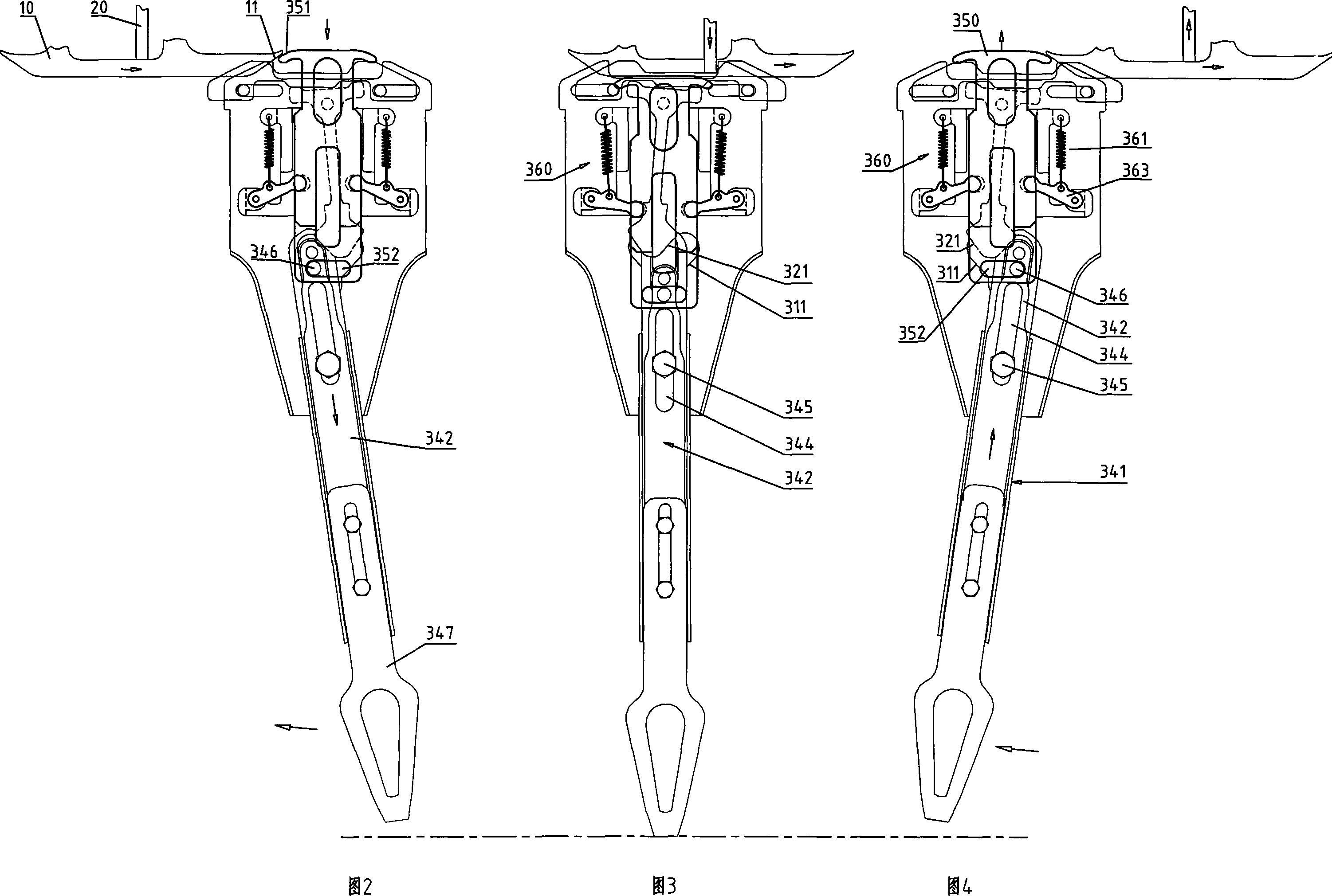
[0019] 1 and 2, the drive plate return assembly 360 composed of spring seat 362, return lever 363 and return tension spring 361 is installed on the symmetrical two sides of the upper drive plate 350 of the bottom plate 310, and one end of the return lever 363 It is hinged on the spring seat 362 (or the bottom plate 310), and its other end is embedded in the groove 353 on the rear side of the drive plate. One end of the return tension spring 361 is connected to the spring seat 362 , and the other end is connected to the return driving rod 363 . The transmission plate 350 can slide between the two spring seats 362 , and one end of the return lever 363 is embedded in the groove 353 on the rear side of the transmission plate 350 . The yarn feeder assembly 340 is connected to the bottom of the base plate 310, and the guide plate 342 on its top is provided with a slide pin 346 on its fron...


PUM


Abstract

The invention relates to an adjustable swing controlling mechanism of a weft nozzle of an intarsia shuttle box, which comprises a bottom plate, a weft nozzle component part which is connected on the lower portion of the bottom plate, a driver plate which is positioned on the upper side of the weft nozzle component part and driver plate return component parts which are positioned on two sides of the driver plate, wherein the driver plate and the weft nozzle component part proceed on slip connection via a chute and a sliding pin which are respectively arranged on the driver plate and the weft nozzle component part which comprises a weft nozzle driver plate, a guide plate and a guide wheel, wherein a weft nozzle is arranged on the lower end of the weft nozzle driver plate, the guide wheel is hinged on the upper end of the guide plate which is glidingly connected on the weft nozzle driver plate and is provided with the chute, a shaft pin which drills through the chute and the weft nozzle driver plate are fixed on the bottom plate, the guide plate slips relative to the shaft pin via the chute and enables a weft nozzle plate to rotate around the shaft pin. The adjustable swing controlling mechanism has the advantages of simple structure, easy forced balance on two sides and convenient assemblage and debugging, has the accuracy of feeding movement which excels the prior technology.

Description

technical field [0001] The invention relates to a computerized flat knitting machine, in particular to a device for controlling the stretching and swinging of a yarn feeder of an intarsia shuttle box. Background technique [0002] When weaving intarsia patterns, according to the computer program, the shuttle boxes that guide the yarns of different colors sequentially feed the yarns to the knitting needles on the needle bed. Therefore, a number of shuttle boxes are arranged on the shuttle bar to guide the weaving yarns of different colors to meet the color requirements of the intarsia pattern. The shuttle box participating in weaving is driven by the shuttle box drive mechanism installed on the machine head, and the random head moves along the shuttle bar. The yarn feeder at the lower end of the moving shuttle box is in the lower position so as to be close to the knitting needles, and the knitting needles for intarsia knitting needle for yarn feeding. When intarsia knitting...

Claims


Application Information

Patent Timeline
IPC IPC(8): D04B15/00D04B15/48D04B15/66D04B15/96
Inventor 冯加林巫友群
Owner 冯加林
Why Eureka
Try Eureka