Eureka AIR delivers breakthrough ideas for toughest innovation challenges, trusted by R&D personnel around the world.

Orthopedic trauma bone plate kit

A bone plate and component technology, applied in the field of bone plates and systems, can solve problems such as unbalanced load transfer, and achieve the effects of saving surgical time, improving fixability, and reducing manufacturing costs

Inactive Publication Date: 2008-08-27
DEPUY PROD INC
View PDF4 Cites 8 Cited by
  • Summary
  • Abstract
  • Description
  • Claims
  • Application Information

AI Technical Summary

Problems solved by technology

Alternatively, reconstruction grid implants can have large gaps between various parts of the reconstruction grid and the bone surface, resulting in uneven load transfer between the bone and reconstruction grid structure

Method used


Image

  • Orthopedic trauma bone plate kit
  • Orthopedic trauma bone plate kit
  • Orthopedic trauma bone plate kit

Examples


Embodiment Construction

[0076] Embodiments of the invention and their advantages are best understood by referring to the ensuing description and drawings, wherein like numerals are used to indicate like and corresponding parts of the drawings.

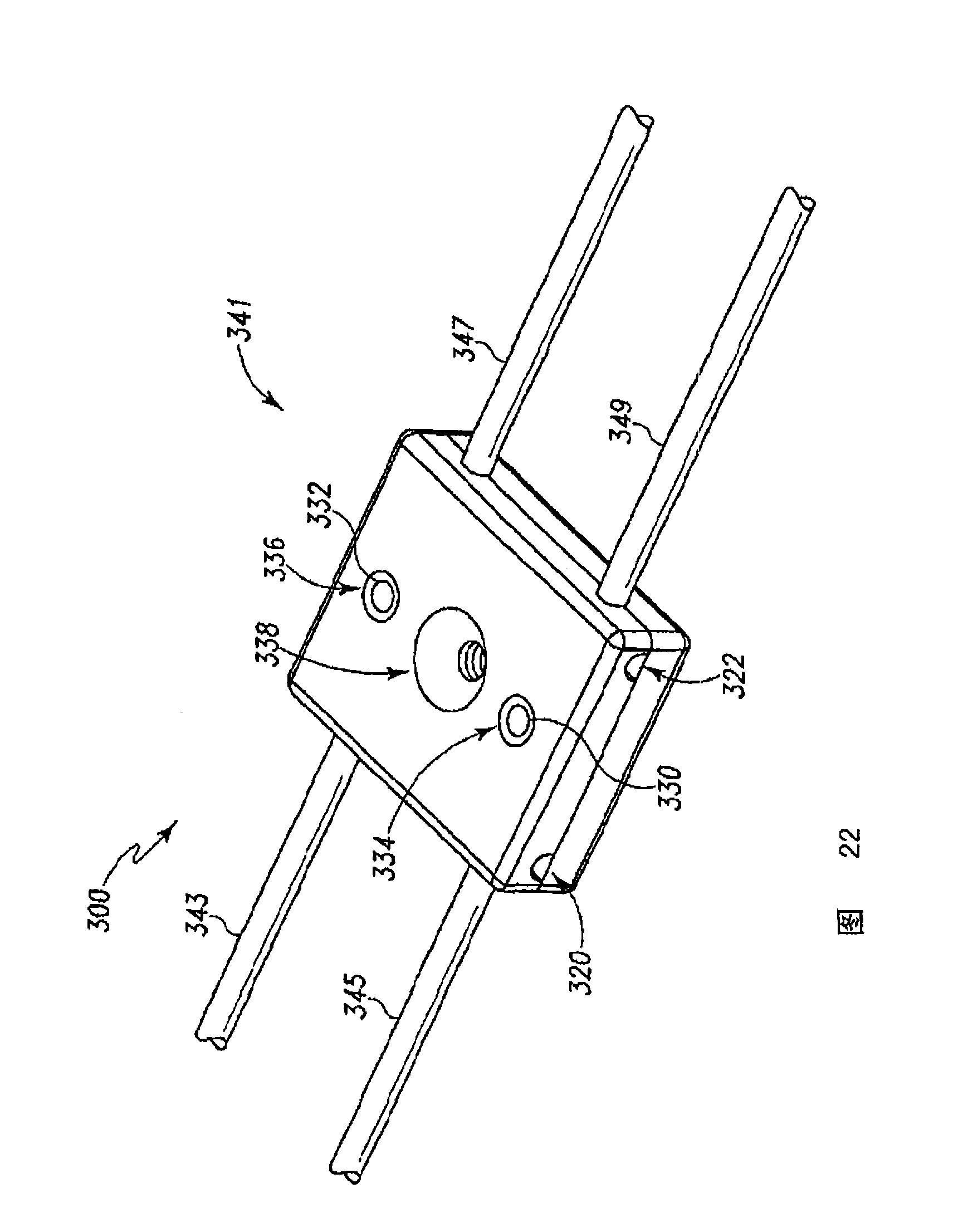
[0077] Referring now to FIG. 1 , there is shown a bone plate assembly 100 in accordance with the present invention. Bone plate assembly 100 is used to engage bone during trauma surgery. For example, bone plate assembly 100 may be used to form bone plate assembly 102 .

[0078] As shown in FIG. 1 , bone plate assembly 100 includes a first plate component 104 . The first plate part 104 will have an appropriate shape and may have a shape suitable for contact with the condyle portion of the bone 2 as shown in FIG. 1 . For example, the first plate member 104 will have a generally truncated triangle so that the contact surface 106 of the plate member 104 can conform to the condyle portion of the bone.

[0079] The bone plate assembly 100 may further include a co...


PUM


Abstract

A kit for the construction of a bone plate assembly for fixation of a fractured bone includes a plurality of plate members, a connecting member for retaining the plurality of plate members in a desired configuration and a plurality of locking members for securing the plate members to the connecting member.

Description

technical field [0001] This application relates generally to the field of orthopedic surgery, and more particularly to osteosynthetic plates and systems for the fixation and compression of fractured or otherwise damaged bones. This application is related to US Patent Application 11 / 527,951, filed September 27, 2006 and entitled "Flexible Bone Fixation Device," which is incorporated herein by reference in its entirety. Background technique [0002] Bone plates used for internal fixation of fractured bones should generally conform to the contours of the surface of the fractured bone. This is especially true for compression plates that are threaded to bone. Matching the Plate Shape to the Bone Contour It is important to compress the plate so that the proper load can be distributed between the bone and the plate when treating a fracture. The bone plate must also have low smoothness and be able to blend with the bone surface as much as possible so as not to irritate or interfer...

Claims


Application Information

Patent Timeline
IPC IPC(8): A61B17/58
CPCA61B17/865A61B17/8023A61B17/8066A61B19/0271A61B17/7044A61B17/8085A61B17/86A61B17/8047A61B50/33
Inventor D·R·舒尔策J·F·龙P·R·普拉萨德M·E·鲁林
Owner DEPUY PROD INC
Why Eureka
Eureka Blog
Learn More