
Ultrasonic imaging system self-adaption beam former based on correlation analysis

An adaptive beam, ultrasonic imaging technology, applied in ultrasonic/sonic/infrasonic diagnosis, sonic diagnosis, infrasonic diagnosis, etc., can solve the problems of inability to dynamically adjust, the side lobe effect cannot be fully suppressed, and the focusing effect is affected.

Inactive Publication Date: 2008-08-13
HARBIN INST OF TECH
View PDF0 Cites 21 Cited by
  • Summary
  • Abstract
  • Description
  • Claims
  • Application Information

AI Technical Summary

Problems solved by technology

It can be seen that the traditional beamformer cannot fully suppress the sidelobe effect caused by the random phase error between channels, and cannot dynamically adjust with the change of the detection position, thus affecting the focusing effect

Method used

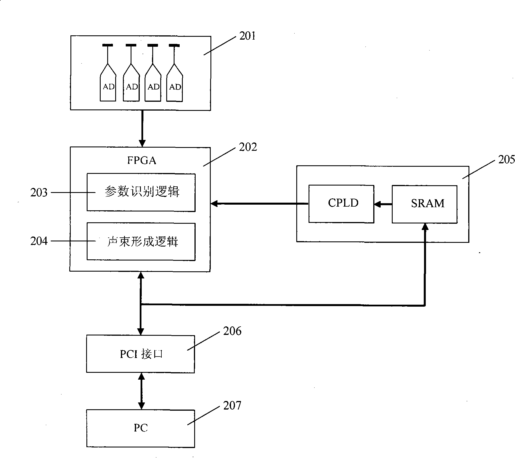
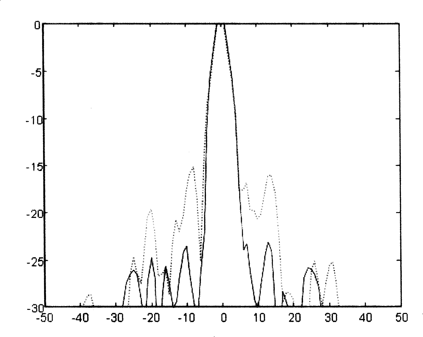

Image

  • Ultrasonic imaging system self-adaption beam former based on correlation analysis
  • Ultrasonic imaging system self-adaption beam former based on correlation analysis
  • Ultrasonic imaging system self-adaption beam former based on correlation analysis

Examples


Embodiment Construction

[0051] The specific embodiments of the present invention will be further described in detail below in conjunction with the accompanying drawings.

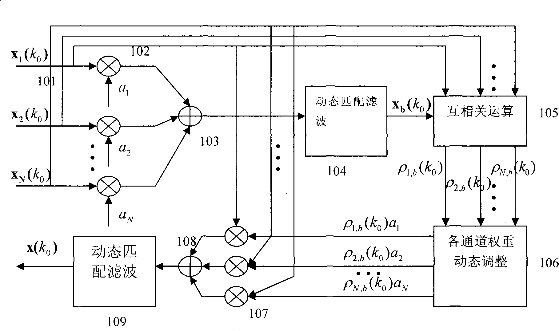
[0052] The block diagram of the whole adaptive beamformer is as follows: figure 1 shown. After the echo signal enters the adaptive beamformer, it is first buffered in the first-in-first-out (FIFO) buffer 101, and after buffering, it is divided into three ways of processing: one way uses the traditional method to perform beamforming, and the other way performs cross-correlation calculation with the reference signal, The other channel waits for the adjusted channel weight coefficient to be calculated and then performs adaptive beamforming. In the traditional beamforming process, the echo signal of each channel is first multiplied by the window coefficient of the fixed window through the multiplier 102, and then accumulated by the accumulator 103. The accumulated sum is the composite value of the traditional beamforming method, and t...


PUM


Abstract

An adaptive beamforming device belongs to medicine ultrasound imaging field. The invention provides an adaptive beamforming technique based on correlativity analysis, directing towards the difficulty that the traditional beamforming device can not completely restrain sidelobe effect resulted from interchannel random phase error and not affect the focusing effect along with the dynamic alignment of detection position. The technique divides the echo signal obtained from each channel into several segments, direct towards each segment, firstly the reference signal is obtained by a classical beam forming method, and then the signal of each channel is mutually correlated with the reference signal, furthermore weight of channel in each segment is dynamically adjusted using correlation coefficient, finally signals of each channel are synthesized to obtain final beam output using adjusted weight. The adaptive beamforming device adaptively detects the variance of enviroment using dynamic apodization and restrains the sidelobe effect resulted from interchannel random phase error. The adaptive beamforming device has wide application prospect in ultrasound imaging field.

Description

technical field [0001] The invention relates to the technical field of medical ultrasound imaging, in particular to an adaptive beamformer. Background technique [0002] Ultrasound imaging is a diagnostic method with a wide range of applications. It has the advantages of no damage, no ionizing radiation, and easy use. Beamforming is the most critical link in the ultrasound imaging system, which directly affects the quality of ultrasound imaging. Low sidelobe levels have always been a goal pursued in beamformer design. From the 1960s to the end of the 1980s, ultrasound imaging systems mainly used analog beamforming technology, which was bulky and had low focusing accuracy. In the early 1990s, with the development of large-scale integrated circuits and high-speed, high-resolution analog-to-digital (A / D) converters, digital beamforming technology gradually occupied a dominant position; it uses digital storage technology to process echo signals Sampling and recording, and the...

Claims


Application Information

Patent Timeline
IPC IPC(8): A61B8/00G06F17/10
Inventor 王强沈毅王艳冯乃章王沛东
Owner HARBIN INST OF TECH
Learn More