
Tyre rubber slitter

A slitting and rubber technology, which is applied in the field of slitting machines, can solve problems such as easy damage of knives, time-consuming and labor-consuming, single-sided blades are easy to chip, etc.

Active Publication Date: 2010-06-09
尹家旺
View PDF6 Cites 0 Cited by
  • Summary
  • Abstract
  • Description
  • Claims
  • Application Information

AI Technical Summary

Problems solved by technology

[0002] The traditional tire rubber slitting is cut by manual or mechanical single-sided knife. The single-sided knife is easy to be chipped, blunt, and easily damaged. It needs to be sharpened and changed frequently, which is time-consuming, labor-intensive, low in efficiency, and high in cost. It can cut soft and thin materials, but cannot cut thick, hard and sticky rubber in strips

Method used

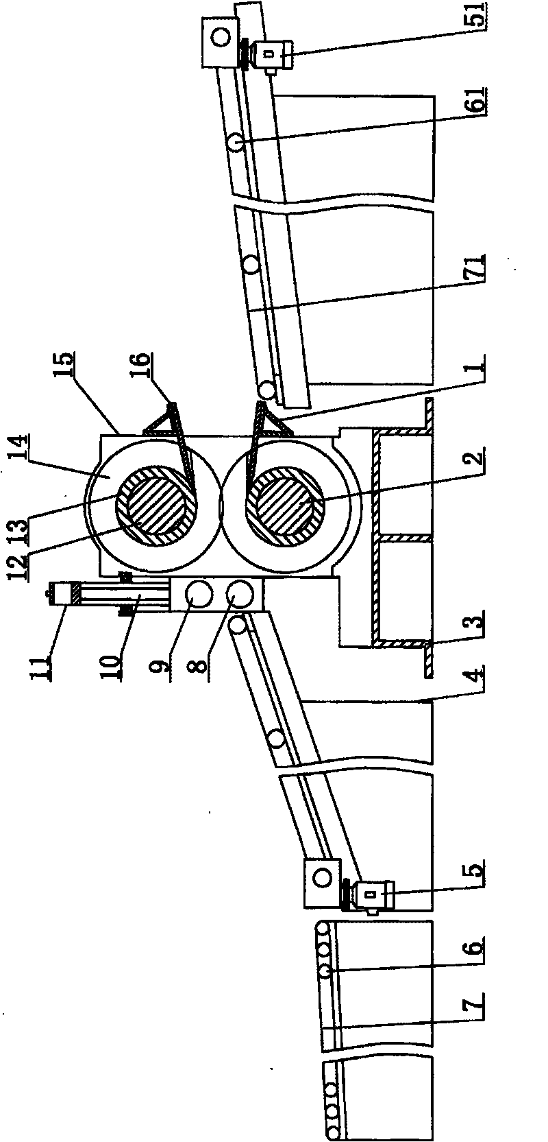
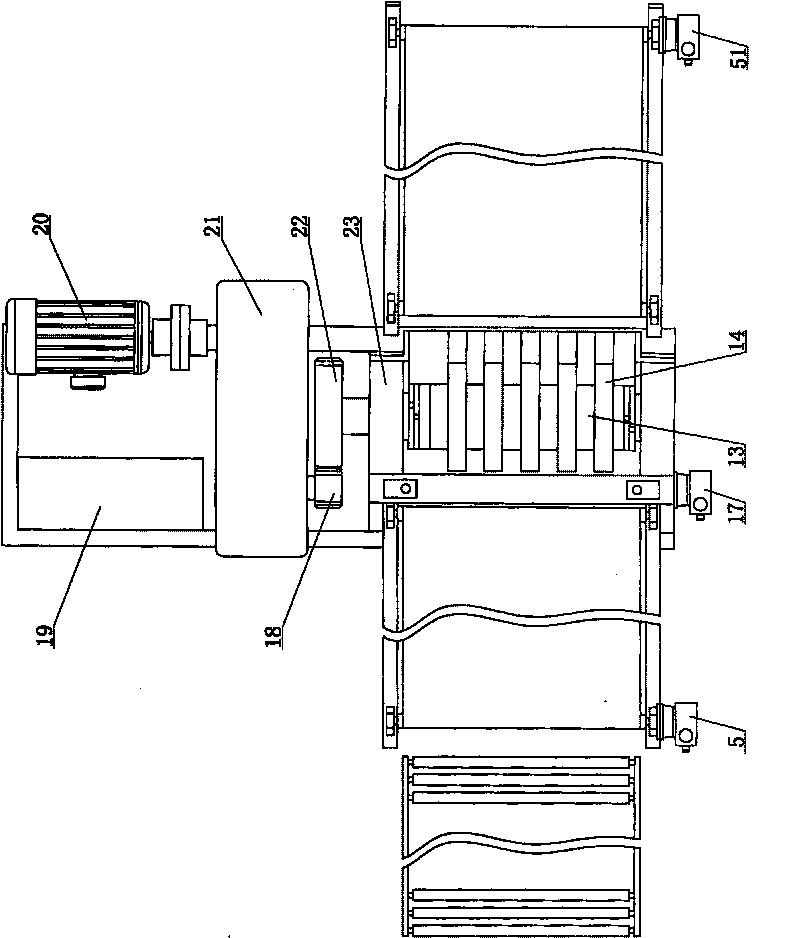
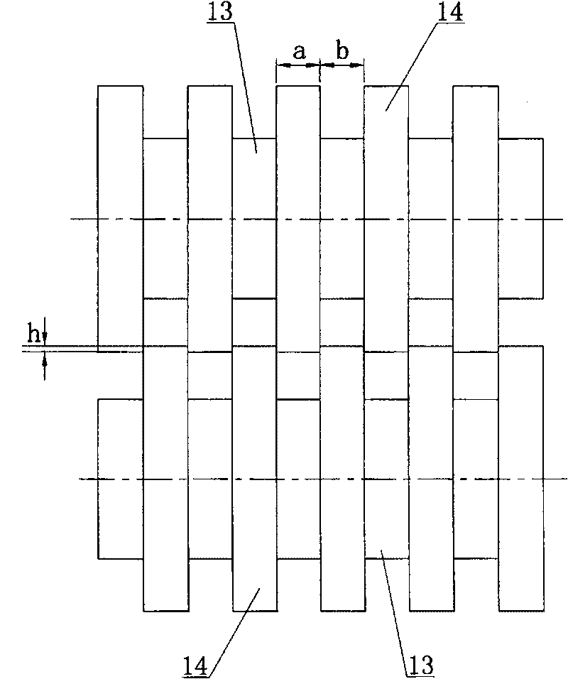

Image

  • Tyre rubber slitter
  • Tyre rubber slitter
  • Tyre rubber slitter

Examples


Embodiment Construction

[0011] The present invention will be further described below in conjunction with the accompanying drawings and specific embodiments.

[0012] figure 1 , 2 Among them, the tire rubber slitting machine is composed of a feeding conveying mechanism, a hydraulic forced feeding mechanism, a slitting mechanism, a material discharging conveying mechanism and an electric control box 19. The feeding conveying mechanism is installed at the front end of the feeding port of the slitting mechanism, and The material conveying mechanism is installed at the rear end of the discharge port of the slitting mechanism. The feeding conveying mechanism and the discharging conveying mechanism include bracket 4, stepless speed regulating reducer 5, 51, conveying roller 6, 61, conveyor belt 7, 71, stepless speed regulating reducer 5, 51 drives conveying roller 6, 61 Drive the conveyor belt 7,71 to run, and the conveying speed is arbitrarily adjusted within a certain range by the stepless speed regulat...


PUM


Abstract

The invention provides a vertical cutting machine for tyre rubber, which comprises a feed-in transporting mechanism, a vertical cutting mechanism and a discharging transporting mechanism, wherein, anend of a feed inlet of the vertical cutting mechanism is provided with a hydraulic forced conveying mechanism so as to provide convenience to convey ultra-thick rubber matrix into the vertical cuttingmechanism by force and raise work efficiency with safety and reliability. The vertical cutting mechanism comprises a frame, an upper cutter axle, a lower cutter axle, an upper rubber shoveling plate,a lower rubber shoveling plate, a drive motor and a reducer, wherein, the upper and lower cutter axles are arranged on a bottom seat of the frame through two bearing seats at both ends of the axles;a plurality of cylindrical cutter discs are positioned on the upper and lower cutter axles in a staggered way through interval sleeves; the upper and lower cylindrical cutter disc groups conduct pressing and cutting for the tyre rubber and can continuously cut the rubber materials with different types of thickness, hardness and viscosity into a plurality of rubber material strips at a time, with uniform discharging and high cutting efficiency. As the rubber material with the length of 10-15 meters can be cut per minute and the labor intensity is reduced, the work efficiency is greatly improvedwith labor and time saved as well as low loss and uneasy wear.

Description

technical field [0001] The invention relates to a tire rubber slitting machine, in particular to a slitting machine for slitting engineering radial tire tread rubber. Background technique [0002] The traditional tire rubber slitting is cut by manual or mechanical single-sided knife. The single-sided knife is easy to be chipped, blunt, and easily damaged. It needs to be sharpened and changed frequently, which is time-consuming, labor-intensive, low in efficiency, and high in cost. It can cut soft and thin materials, but cannot cut thick, hard and sticky rubber in strips. Contents of the invention [0003] In order to overcome the deficiencies of the above-mentioned prior art, the object of the present invention is to provide a slitting machine that is not easy to chip, has low wear, does not blunt the knife, does not need to be changed frequently, and adopts a double-sided cylindrical cutter head to squeeze and cut tire rubber. [0004] The technical solution adopted in t...

Claims


Application Information

Patent Timeline
Patent Type & Authority Patents(China)
IPC IPC(8): B26D1/24B26D5/08B65H20/02
Inventor 尹家旺
Owner 尹家旺
Learn More