Light source for high efficiency illumination systems

A light beam and filament technology, applied in the field of lighting systems, can solve problems such as light waste

Inactive Publication Date: 2008-07-23
GENERAL ELECTRIC CO
View PDF0 Cites 0 Cited by
  • Summary
  • Abstract
  • Description
  • Claims
  • Application Information

AI Technical Summary

Problems solved by technology

In this case a small amount of light is wasted at each end of the light source 3, but in addition the aperture 5 will also have a large unfilled area, so that black streaks will also appear in the emitted light beam

Method used


Image

  • Light source for high efficiency illumination systems
  • Light source for high efficiency illumination systems
  • Light source for high efficiency illumination systems

Examples


Embodiment Construction

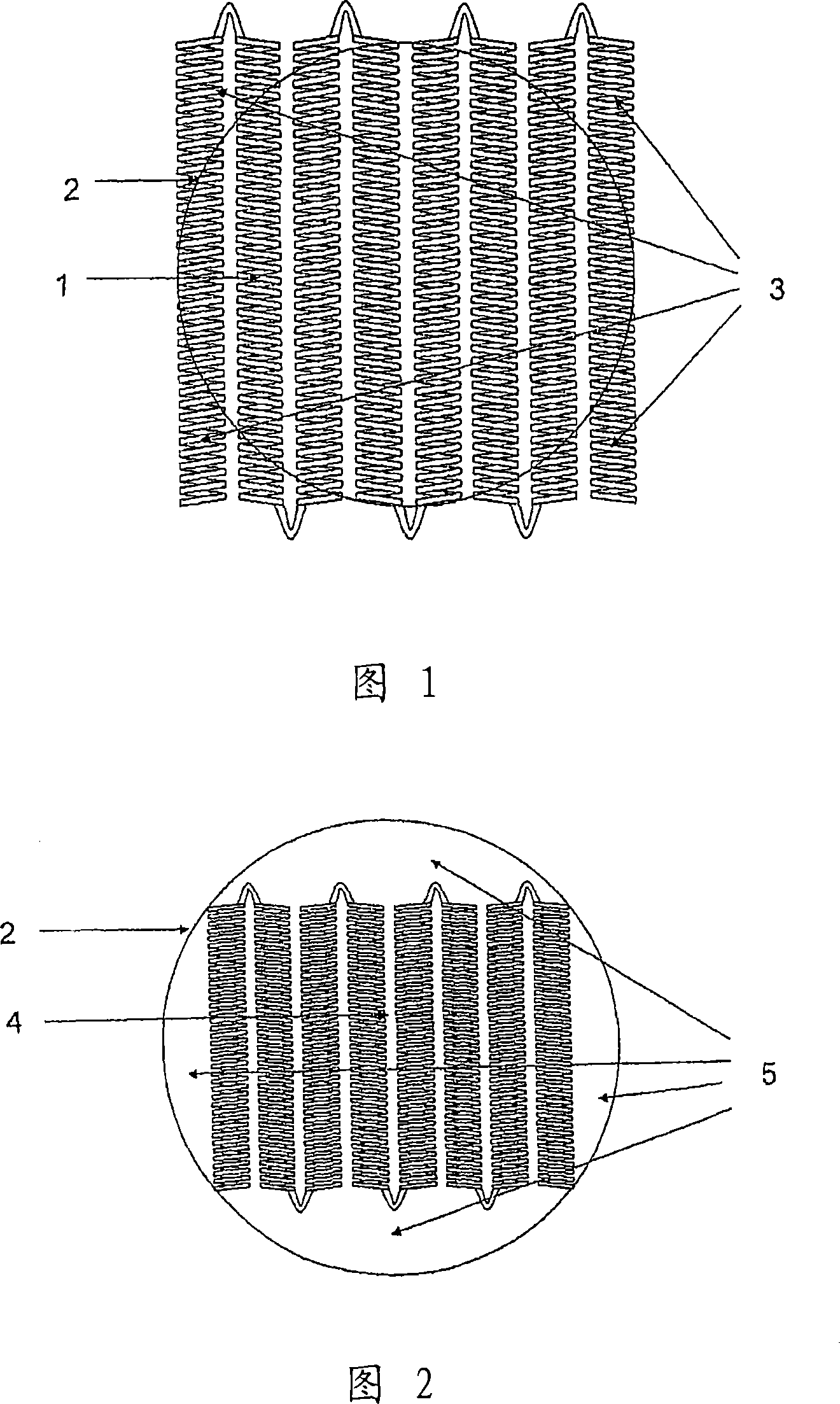
[0024] An exemplary embodiment of the present invention in which the light source is an incandescent filament will be described below with reference to FIG. 4 . Fig. 4 shows a view of the monoplanar incandescent filament array of the present invention as viewed from a position perpendicular to the spherical reflector. Referring to Fig. 4, it can be seen that the filament array comprises eight parallel helically wound coil sections. The outer filament section 7 is considerably shorter than the inner filament section 8, while the intermediate section 9, 10 between the outer and inner sections has an intermediate length. And the circle 11 shown in this figure represents the aperture through which the light emitted from this filament array will have to pass. It can be seen that each portion has a length that exceeds the boundaries of the circle. The fraction of the filament that emits light that would not pass through the aperture and would therefore be wasted, corresponding to t...


PUM


Abstract

A filament array for an incandescent lamp comprises a plurality of helically-coiled filament sections (7-10), which are arranged in one or more planes. The filament sections are of varying lengths whereby the array approximates the cross-sectional shape of the light beam which is to be projected by the lamp, as indicated for example by the circle (11).

Description

technical field [0001] The present invention relates generally to lighting systems, and in particular to systems utilizing spherical or near-spherical reflectors to gather light from a suitable source and exit the light to produce a high intensity beam. In this type of system, the light source is placed in front of the reflector and the center of mass of the light source is at the focus of the reflector. The light thus exits either directly from the light source or after being reflected by the reflector. The outgoing light then needs to be processed with a set of lenses, apertures, and other optics to produce a beam with certain desired properties, depending on the desired beam properties. Background technique [0002] Illumination systems utilizing spherical or near-spherical reflectors can be divided into several categories, depending on the characteristics of the beam produced and the manner in which it is produced. There are many such systems, the three most common exa...

Claims


Application Information

Patent Timeline
Patent Type & Authority Applications(China)
IPC IPC(8): H01K1/14H01K7/02
CPCH01K1/14
Inventor 安德鲁·戴维斯罗杰·A·休姆
Owner GENERAL ELECTRIC CO
Why Eureka
Try Eureka