Method for testing fluid bed reactor distributing plate

A technology of a fluidized bed reactor and a detection method, which is applied in the direction of using sound waves/ultrasonic waves/infrasonic waves to analyze fluids, etc., which can solve problems such as system flow and reaction influence, human injury, and differential pressure gauge blockage, and meet the requirements of low measurement conditions. Easy and convenient installation, small measurement error

Inactive Publication Date: 2011-08-31
CHINA PETROLEUM & CHEM CORP +1
View PDF0 Cites 0 Cited by
  • Summary
  • Abstract
  • Description
  • Claims
  • Application Information

AI Technical Summary

Problems solved by technology

[0007] At present, the performance inspection of the distribution plate in the factory is mainly reflected indirectly through the smooth operation of the production process and the stability and reliability of the product quality. The differential meter is often blocked during the measurement process, resulting in false reports and false reports; the identification of the fluidization state is mainly judged by the pressure pulsation signal, but it is still in the laboratory stage
The ray method, light detection method and other methods mainly investigate the growth, coalescence and rupture behavior of the bubbles above the distribution plate, and cannot specifically detect the dead zone, agglomeration and blockage of the plate hole and / or hood on the distribution plate. It is even more impossible to identify the flow state in the process of particle fluidization
At the same time, the light detection method also needs to extend the light source into the fluidized bed, which may affect the internal flow field and affect the flow and reaction inside the system
The ray method is fatal to the human body

Method used


Image

  • Method for testing fluid bed reactor distributing plate
  • Method for testing fluid bed reactor distributing plate
  • Method for testing fluid bed reactor distributing plate

Examples


Embodiment 1

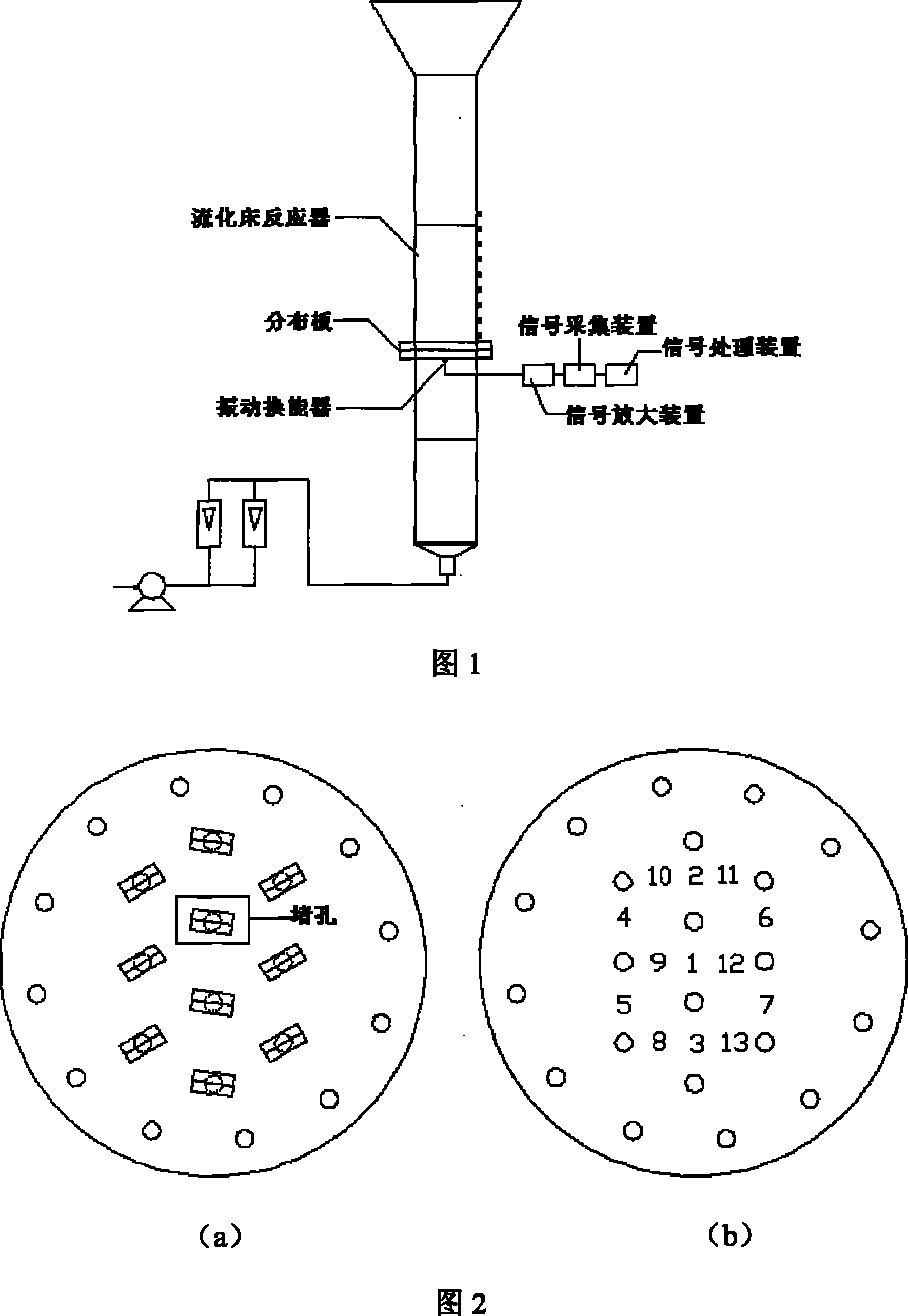
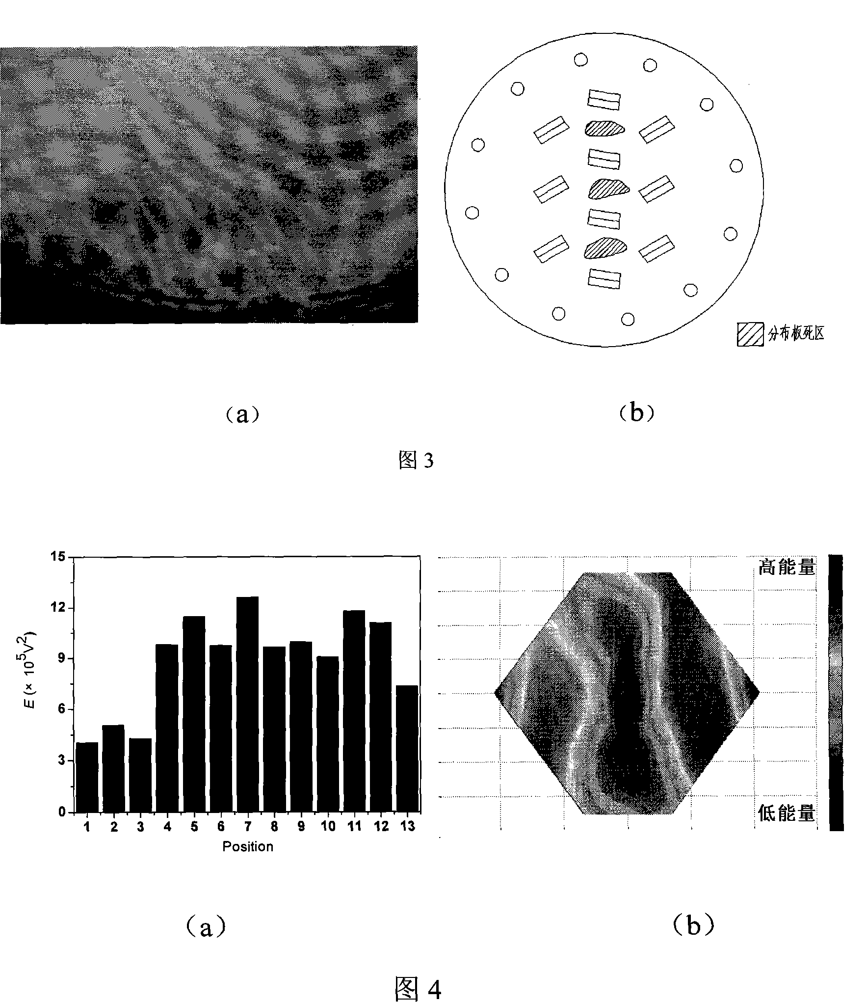
[0052] use as figure 1 Device diagram, in a gas-solid fluidized bed made of plexiglass with a height of 1000mm and an inner diameter of 150mm, with figure 2 The distribution plate shown is the experimental object, the hole diameter is 2.0mm, and the opening ratio is 2.6%. Attached to the distribution plate as image 3 Polyethylene particles distributed as shown on the right to create dead zones and agglomerates. Air is used as the fluidizing gas, the superficial gas velocity is 0.65m / s, and the static bed height is 500mm. Passive acoustic emission sensors are attached to different positions under the distribution board (such as figure 2 ), and the distances from the inlet holes of the adjacent distribution plates are 0.15L, 0.25L, and 0.5L respectively, where L is the minimum hole spacing of the distribution plate. The sampling frequency is 200kHz, and the sampling time is 5s.

[0053] The energy analysis of the acoustic emission signal is obtained as Figure 4 The ene...

Embodiment 2

[0055] use as figure 1 Device diagram, in a gas-solid fluidized bed made of plexiglass with a height of 1000mm and an inner diameter of 150mm, with figure 2 The distribution plate shown is the experimental object, the hole diameter is 2.0mm, and the opening ratio is 2.6%. Air is used as the fluidizing gas, the superficial gas velocity is 0.65m / s, the static bed height is 500mm, the sampling frequency is 95MHz, and the sampling time is 5s. Also first measure the acoustic emission signals at 13 points below the distribution plate when all the hoods are working normally, and then block a plate hole or hood above the center of the distribution plate (such as figure 2 ), and then measure the acoustic emission signals at the same 13 points below the distribution plate. Passive acoustic emission transducers are attached to different positions below the distribution board (such as figure 2 ), and the distances from the inlet holes of the adjacent distribution plates are 0.15L, 0...

Embodiment 3

[0059] use as figure 1 In the diagram of the device, the gas-solid fluidized bed is transparent organic glass with a height of 3000mm and an inner diameter of 250mm, and the height of the static bed is 800mm. image 3 The distribution plate shown is the experimental object, the hole diameter is 2.0mm, and the opening ratio is 2.6%. Using air as the fluidizing gas, the gas velocity changes from 0 to 0.8m·s -1 . The operating temperature is room temperature. The sampling frequency is 800kHz, and the sampling time is 10s. The passive acoustic emission transducer is attached to position 1 under the distribution board.

[0060] Measure the acoustic signal generated by the fluidization of particles with an average particle diameter of 0.64mm as the gas velocity gradually increases. The energy ratio and variance ratio of the acoustic signal are basically stable at about 1 to 2 with the change of air velocity. When the gas velocity reaches the critical fluidization velocity, the...


PUM

PropertyMeasurementUnit
particle sizeaaaaaaaaaa
pore sizeaaaaaaaaaa
porosityaaaaaaaaaa

Abstract

The invention discloses a distributing plate detection method of fluidized bed reactor, which comprises (1), arranging at least one acoustic emission signal receiver at non-hole portion under the distributing plate of fluidized bed, (2), the acoustic emission signal receiver receives the acoustic emission signal generated by the impact between the internal particles of the fluidized bed reactor and the distributing plate, (3), selecting the acoustic emission signal on the distributing plate, (4), judging the block condition of hole or windshield on the distributing plate according to the frequency F, amplitude A or energy E of the acoustic emission signal on the distributing plate, finding critical fluidizing speed, initial bubbling speed, critical turbulence speed, quick fluidizing speedand particle carryover speed according to the energy E change of the acoustic emission signal, using the energy E change of the acoustic emission signal along the discharge direction of the windshield to obtain the maximum jet distance of the windshield on the distributing plate. The inventive vibrator is non-inserting type, with easy installment, safety, environment protection, sensitive reaction, low measurement error and wide application.

Description

technical field [0001] The invention relates to the detection of distribution plates of fluidized bed reactors, in particular to a detection method of distribution plates of fluidized bed reactors. Background technique [0002] As an important component to ensure good and stable fluidization of the fluidized bed, the distribution plate has a direct effect on the fluidized bed of only 20 to 30 cm, but it has a great influence on the fluidized state quality of the entire fluidized bed and the operating performance of the reactor. have a decisive influence. The main functions of the distribution plate include: [0003] (1) Evenly distribute the fluid while minimizing the energy consumption of the fluid passing through the distribution plate; [0004] (2) Ensure that good gas-solid and liquid-solid contact conditions are formed near the distribution plate, so that all particles are in motion, thereby eliminating dead zones; [0005] (3) The distribution plate is not blocked a...

Claims


Application Information

Patent Timeline
Patent Type & Authority Patents(China)
IPC IPC(8): G01N29/02
Inventor 王靖岱阳永荣任聪静曹翌佳陈杰勋姜晓静徐显骏蒋斌波廖祖维
Owner CHINA PETROLEUM & CHEM CORP
Why Eureka
Try Eureka