Top thread gripper mechanism used for embroidery machine

A clamping mechanism and technology for embroidery machines, which are applied to the mechanism of embroidery machines, embroidery machines, textiles and paper making, etc., can solve the problems of falling off the upper thread, stopping the upper thread, not effectively controlling the thread trimming, and inconsistent length of the thread trimming. , to achieve a fixed and reliable effect

Inactive Publication Date: 2008-07-23
HANGZHOU JINGWEI ELECTRONICS MECHANICAL MFG
View PDF0 Cites 3 Cited by
  • Summary
  • Abstract
  • Description
  • Claims
  • Application Information

AI Technical Summary

Problems solved by technology

[0002] When the embroidery machine is embroidering, due to color change and shutdown, etc., the upper thread will fall off due to factors such as tension and natural wind, and the upper thread will fall out of the pinhole or be wound in a disorderly manner, which will cause trouble for the embroiderer to operate, and cause the length of the thread to be trimmed. Disadvantages such as inconsistency
The current embroidery machine, the upper thread is not effectively controlled when it is stopped and trimmed

Method used


Image

  • Top thread gripper mechanism used for embroidery machine
  • Top thread gripper mechanism used for embroidery machine
  • Top thread gripper mechanism used for embroidery machine

Examples


Embodiment Construction

[0021] The present invention will be further described below in conjunction with the drawings and embodiments:

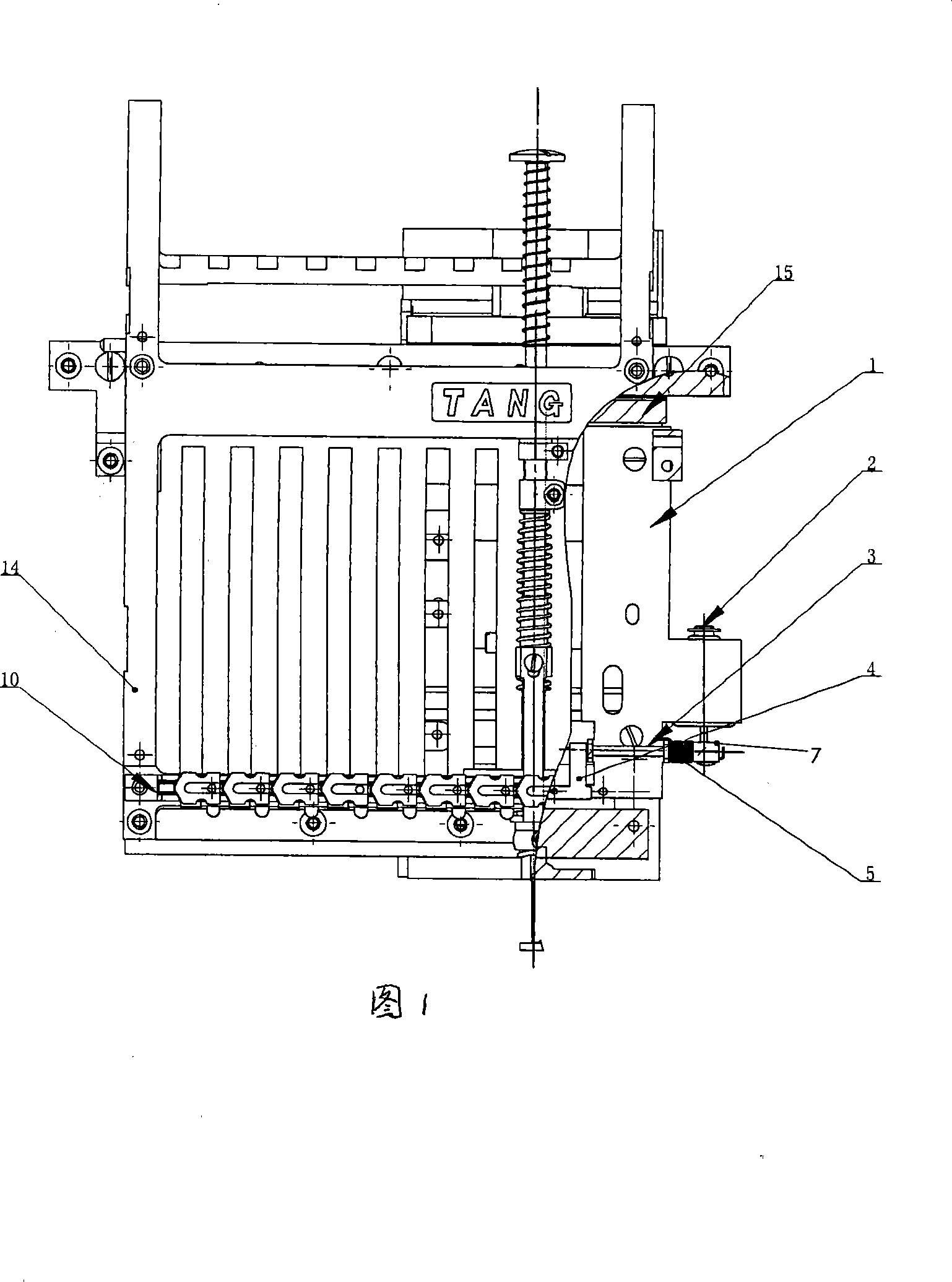
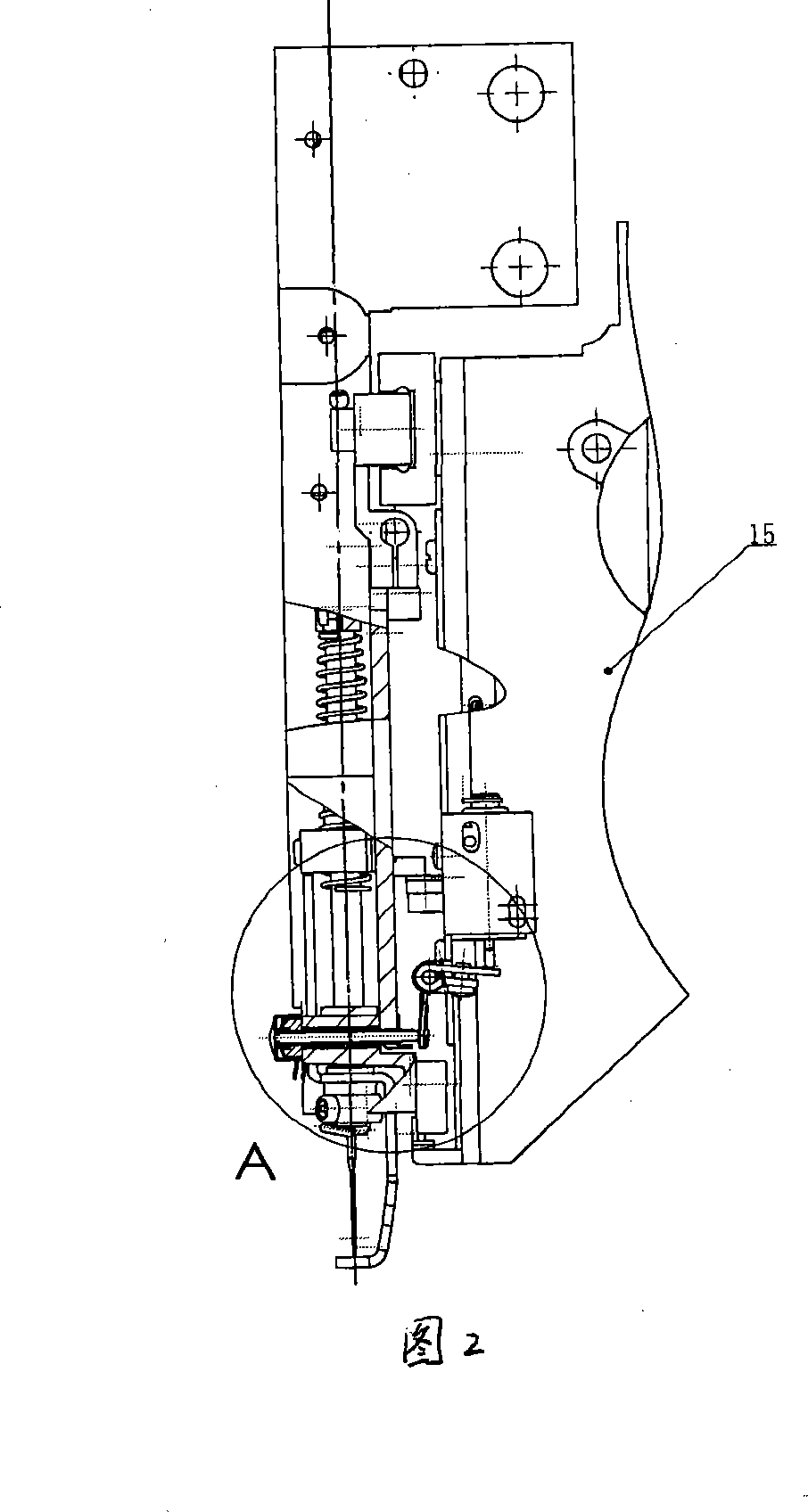
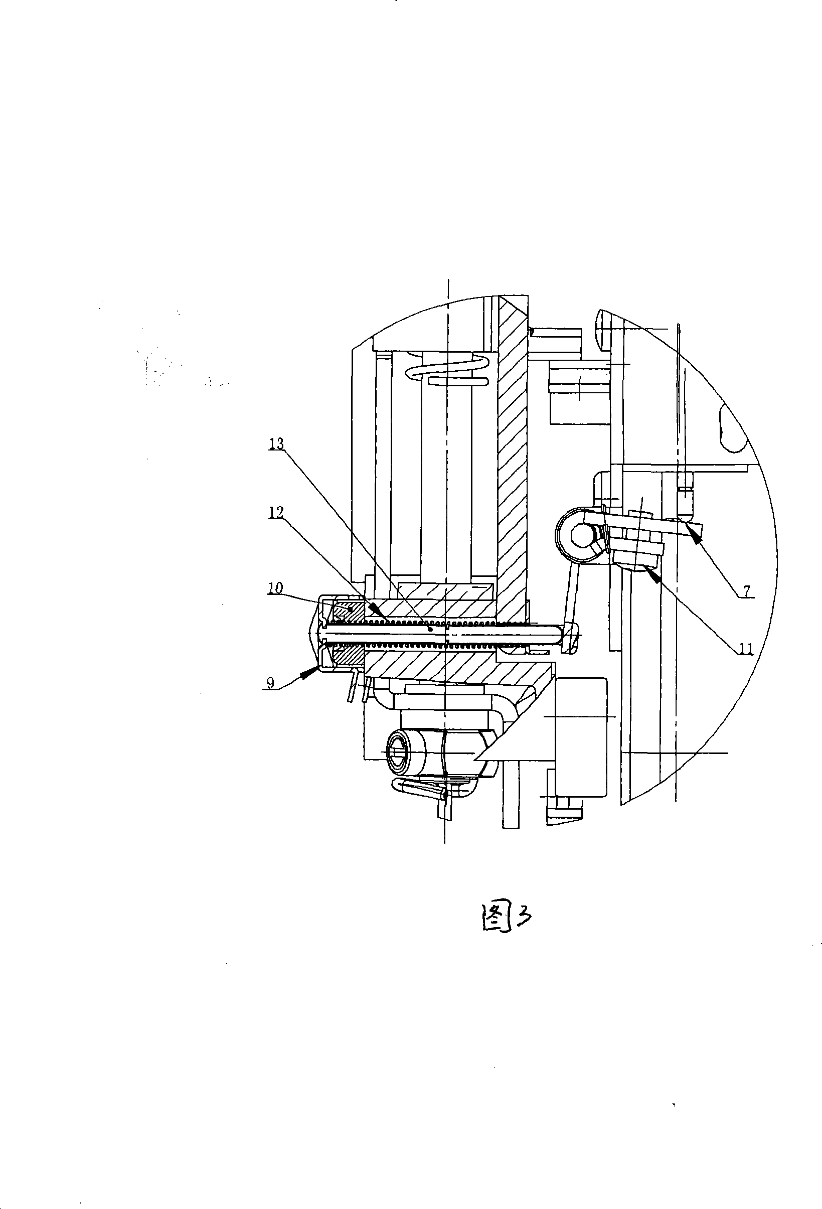
[0022] As shown in the figure, the upper thread clamping mechanism used on the embroidery machine includes a machine head 15 and a needle bar frame 14. An electromagnet seat 1 is installed on the right side of the machine head 15, and an electromagnet is installed on the electromagnet seat 1 2. The electromagnet seat 1 is also equipped with a synchronization shaft 3, one end of the synchronization shaft 3 is fixedly connected with a lever plate 4, the other end of the synchronization shaft 3 is connected with an adjustable lever plate 7, the adjustable lever plate 7 and the electromagnet core shaft 2 One end is mated and connected; the adjustable lever plate 7 is provided with a screw 11 for locking the relative position of the adjustable lever plate 7 and the synchronization shaft 3. When the adjustable lever plate 7 is adjusted to the required angle, it is locked and ...


PUM


Abstract

The invention relates to a surface thread clamping mechanism used on an embroidery machine, comprising a handpiece and a needle bar rack. An electromagnet base is positioned on one side of the handpiece and an electromagnet is positioned on the electromagnet base. A synchronous axle is also positioned on the electromagnet base. One end of the synchronous axle is fixedly connected with a lever plate and the other end is connected with an adjustable lever plate, which is fit-connected with one end of the electromagnet mandrel. A grip slipper is fixed arranged on the needle bar rack, a through hole is positioned on the grip slipper corresponding to the needle position, and a clamping axle and a spring are positioned inside the through hole. The lever plate and one end of the clamping axle are in fit connection. The other end of the clamping axle is fixedly connected with a clamping plate; under the normal state, the grip slipper and the spring are used to press the surface thread on the grip slipper. The surface thread clamping mechanism has the advantages that when the electromagnet is cut off with the power, the surface thread will be clamped by the clamping plate and then the surface thread is controlled to avoid errors. When the embroidery is carried out, only the handpiece embroidery needle clamping plate is open to permit the corresponding surface thread to feed the thread with the movement of the picking thread bar and the other surface threads are clamped by the clamping piece.

Description

Technical field [0001] The invention relates to the field of embroidery machines, in particular to a thread clamping mechanism used on embroidery machines. Background technique [0002] When the embroidery machine is embroidering, due to the color change and shutdown, the upper thread falls off due to factors such as tension and natural wind, detaches from the needle hole or entangles disorderly, which makes the embroidery work troublesome and the length of the thread is trimmed. Disadvantages such as inconsistency. In the current embroidery machine, the upper thread is not effectively controlled when it stops and when the thread is trimmed. To solve the problem, the face line must be controlled. Summary of the invention [0003] The present invention solves the above-mentioned shortcomings of the prior art and provides a needle thread clamping mechanism used on embroidery machines. [0004] The technical solution adopted by the present invention to solve its technical problems:...

Claims


Application Information

Patent Timeline
IPC IPC(8): D05C11/00D05C11/08
Inventor 汤晓明
Owner HANGZHOU JINGWEI ELECTRONICS MECHANICAL MFG
Why Eureka
Try Eureka