
Vertical shaft rotational flow flood discharging tunnel and emptying tunnel or diversion tunnel square crossing arrangement hydraulic form

A diversion tunnel and venting tunnel technology, applied in water conservancy projects, traditional hydropower energy, marine engineering, etc., can solve the problems of loss of wall restraint, water body climbing, etc., to save project cost, speed up project progress, and shorten project. The effect of the construction period

Inactive Publication Date: 2008-07-09
SICHUAN UNIV +1
View PDF0 Cites 21 Cited by
  • Summary
  • Abstract
  • Description
  • Claims
  • Application Information

AI Technical Summary

Problems solved by technology

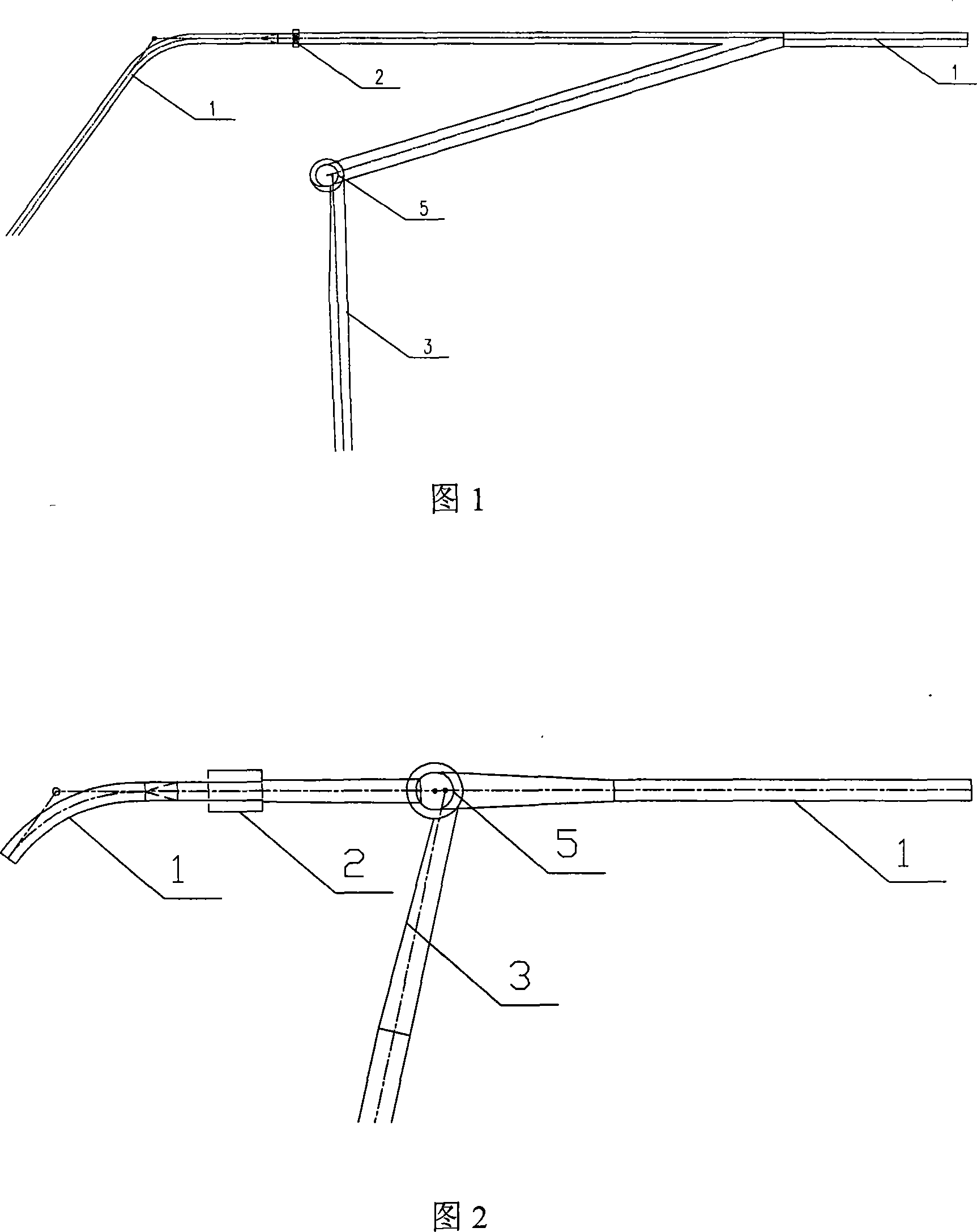
[0005] In actual operation, because the flood discharge tunnel and the emptying tunnel do not operate at the same time, when the water flow in one of the holes flows to the junction of the two holes, one side of the wall suddenly disappears, and the water body loses the restraint effect of the wall, and the water flows horizontally. Diffusion rushes to the other side wall of the vent hole at a certain angle, causing the water body to climb up

Method used


Image

  • Vertical shaft rotational flow flood discharging tunnel and emptying tunnel or diversion tunnel square crossing arrangement hydraulic form
  • Vertical shaft rotational flow flood discharging tunnel and emptying tunnel or diversion tunnel square crossing arrangement hydraulic form

Examples


Embodiment Construction

[0018] Embodiments are given below in conjunction with the accompanying drawings and the present invention is described in detail. It is necessary to point out that the following examples are only used to further illustrate the present invention, and can not be interpreted as limiting the protection scope of the present invention, some non-essential improvements and improvements made by those skilled in the art based on the content of the present invention above. Adjustment still belongs to the protection scope of the present invention.

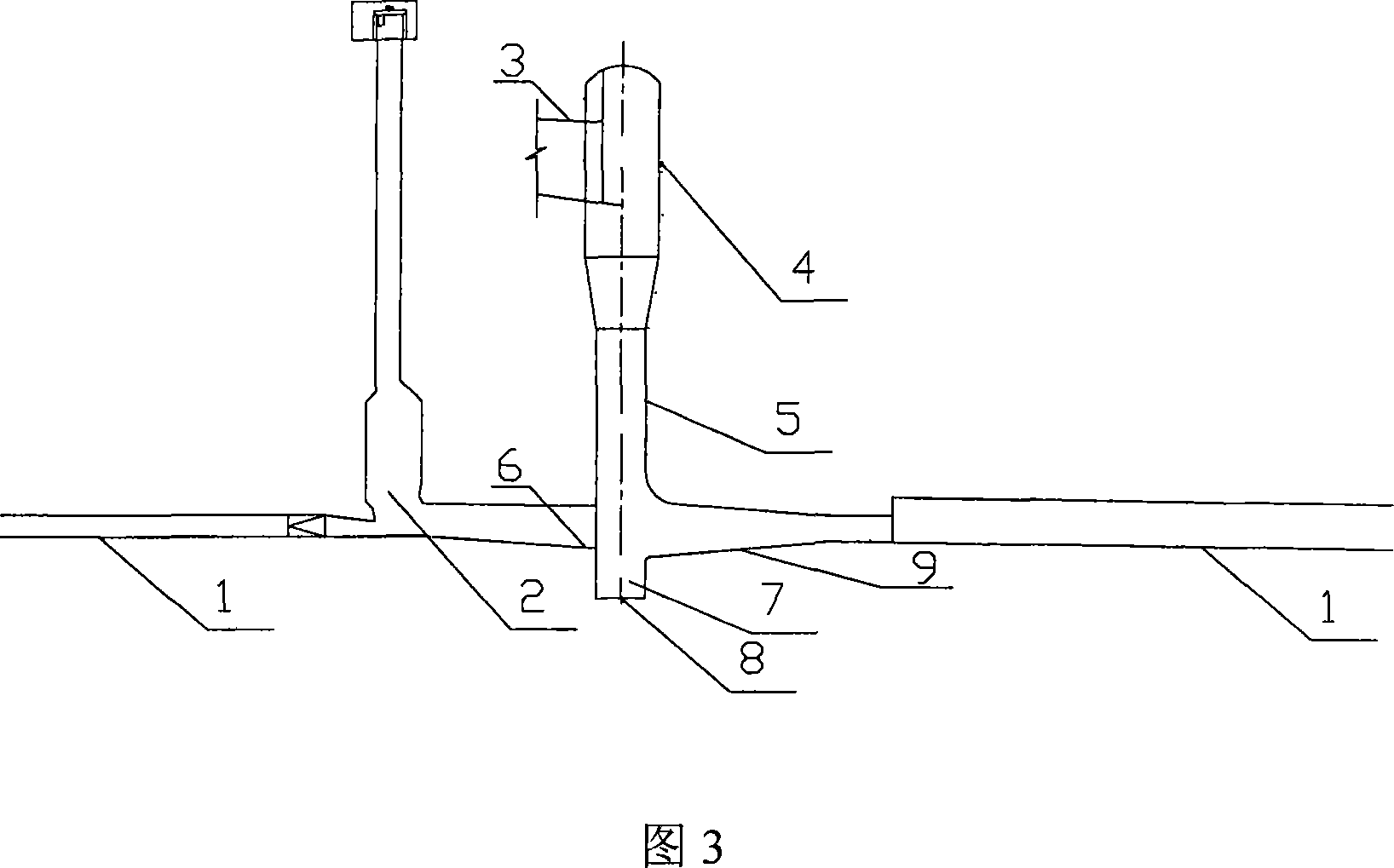
[0019] The embodiment given by the present invention is on the basis of hydraulic facilities composed of vent hole or diversion hole 1 and the spillway tunnel 3 that is provided with vertical shaft swirling energy dissipation, and the vertical shaft 5 that the spillway tunnel 3 is directly passed through is arranged, and The top behind the lock chamber 2 in the vent hole or diversion tunnel 1 below is vertically intersected and connected, so ...


PUM


Abstract

The invention discloses a hydraulic engineering type of a vertical crossing arrangement for a silo vortex flood discharging tunnel and a releasing tunnel or a diversion tunnel, which is characterized in that: the hydraulic engineering type is to make the flood discharging tunnel and the releasing tunnel or a diversion tunnel arranged in vertical crossing through a silo vortex chamber on the top of no pressure section behind a middle brake chamber of the releasing tunnel or the diversion tunnel, which combines the flood discharging tunnel behind the silo with the releasing tunnel or the diversion tunnel. The invention needs not to construct a section of drainage equipment from the silo exit to the connection place of two tunnels, and can avoid bad fluidization in a connection place of two tunnels in the prior inclined crossing technique scheme, has no particular requirements and limitations on the axis direction of the releasing tunnel or the diversion tunnel, can select a good and short path for construction according to the landform and geologic conditions, thereby greatly lowering cost, reducing engineering period, achieving the aim of a rapid start of operations.

Description

technical field [0001] The invention belongs to the technical field of layout forms of flood discharge tunnels and vent holes or diversion tunnels in water conservancy projects, and in particular relates to a brand-new hydraulic form in which vertical shaft swirl flood discharge tunnels and vent tunnels or diversion tunnels are vertically intersected. Background technique [0002] In the design of hydropower stations, due to the needs of the engineering process and the limitations of the local topographic and geological conditions, it is often impossible to arrange diversion tunnels or / and vent tunnels and flood discharge tunnels at the same time, so diversion tunnels will be arranged simultaneously in a water conservancy project Or / and emptying tunnels and flood tunnels, and in order to save costs in the later stage of the project, it will be considered to combine these diversion tunnels or / and emptying tunnels and flood tunnels at a certain position, which is commonly refer...

Claims


Application Information

Patent Timeline
Patent Type & Authority Applications(China)
IPC IPC(8): E02B9/02E02B8/06
CPCY02E10/22Y02E10/20
Inventor 刘新春刘善均陈清波邓军詹国强王韦张建民孙成祥许唯临
Owner SICHUAN UNIV
Learn More