Assembly and method for mounting a pump bearing in/on plastic coolant pump housings

A technology for coolant pumps and pump bearings, which is applied to components of pumping devices for elastic fluids, rigid supports for bearing components, bearings, etc., which can solve problems such as increased processing costs, breakage, and weakened bearing necks, and achieve small Processing and assembly costs, improved service life, and less noise

Inactive Publication Date: 2013-06-19
欧根·施密特博士仪器和泵制造有限责任公司
View PDF2 Cites 0 Cited by
  • Summary
  • Abstract
  • Description
  • Claims
  • Application Information

AI Technical Summary

Problems solved by technology

However, this design, which has been proven in practice, entails increased processing costs for the production of the "adhesive ring", because for the "processing" of the adhesive ring in the plastic housing, the surrounding housing groove must also be inserted mechanically afterward, including for the Holes needed to "fill this shell slot"
[0015] The radial housing groove to be arranged in the plastic housing of the coolant pump has the effect of weakening the bearing journal due to the arrangement of this housing groove, so that there is a risk of breaking at this point under external belt loads
[0016] On the other hand, the injection of polyamide into the annular intermediate space formed by the housing groove and the bearing groove through the access hole requires precise dosing of the injection quantity and also precise control of the filling, since the polyamide, for example, can be axially aligned in the direction of the shaft seal. Upflow, which may adversely affect the sealing function of the radial sealing ring or sliding ring, or incomplete filling of the ring groove also significantly limits the desired axial and radial fixation of the bearing in the plastic housing
[0017] However, the arrangement of the short arms proposed in the above-mentioned application in the bearing bore of the plastic housing with the short arm groove in between in combination with the access hole and the housing groove does not lead to the desired strength of the bonded connection in practice, because by Adhesives with viscous liquids do not guarantee complete filling of the ring and jib grooves
Therefore in practice only solutions with one access hole to the ring groove can be realized

Method used


Image

  • Assembly and method for mounting a pump bearing in/on plastic coolant pump housings
  • Assembly and method for mounting a pump bearing in/on plastic coolant pump housings

Examples


Embodiment Construction

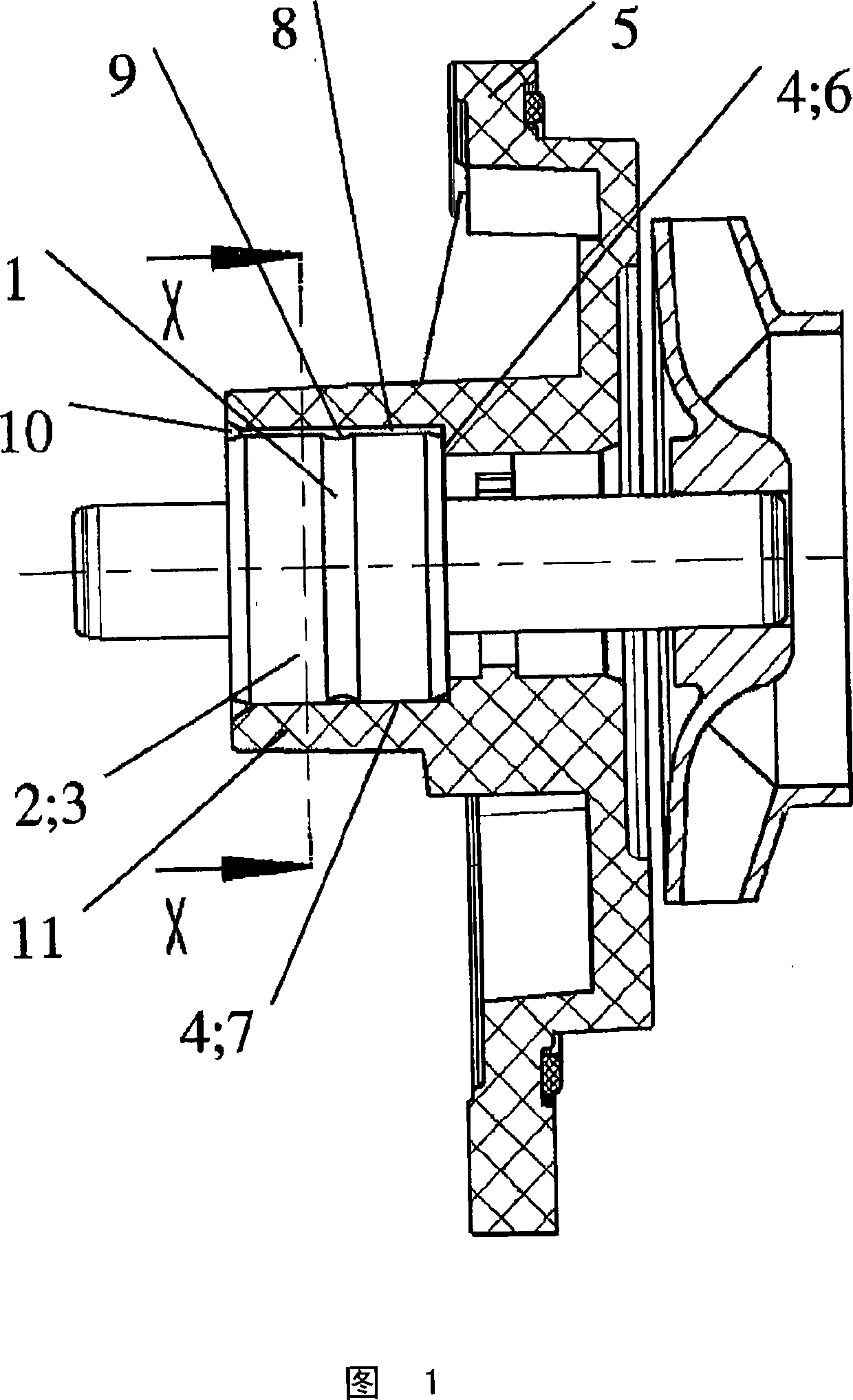
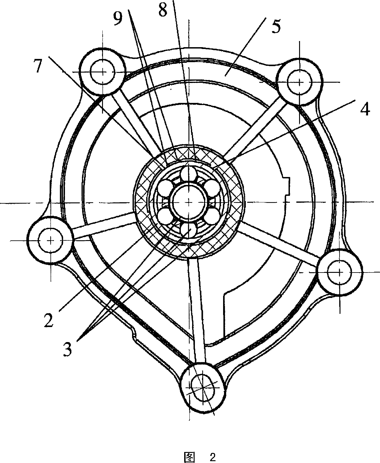
[0046] exist figure 1 A possible design of the structure according to the invention is shown in a side view, a sectional view. figure 2 show according to figure 1 The dependent cross-sectional view X-X.

[0047] Here, a bearing ring 2 of a pump bearing 3 with at least one bearing groove 1 is arranged in a bearing seat 4 of a plastic coolant pump housing 5 . The bearing seat 4 is composed of many positioning short arms 7 combined with axial bearing shoulders 6 .

[0048] Between the positioning short arm 7 and the bearing shoulder 6, there are separate, i.e. independent, adhesive grooves 8, which are respectively equipped with liquid-tight walls 9 in four axial directions, that is, they have no connecting channels between them. .

[0049] Only above this adhesive groove 8, ie at the bearing ring 2 of the pump bearing 3 arranged there, also at the outer edge of the pump bearing 3, at the slot-shaped points of the adhesive pocket 10, is the adhesive. The contact tank is "op...


PUM


Abstract

The assembly includes a pump bearing ring that is fitted with at least one bearing groove and is disposed in / on a bearing seat of a plastic coolant pump housing with an axial bearing collar, and several positioning webs which are located on the bearing seat. Separate adhesive grooves are placed between the positioning webs and the bearing collar. The adhesive grooves are provided with liquid-tight walls in four of the axial directions, an opening in the direction of the pump bearing ring, and slot-shaped adhesive pockets in the area of the outer edge of the pump bearing. A method for mounting a pump bearing in / on a plastic coolant pump housing includes steps of spreading adhesive on a bearing ring, pressing the bearing ring into / onto the bearing seat, and inductively heating the pump bearing in the plastic coolant pump housing.

Description

technical field [0001] The invention relates to an arrangement and a method for arranging pump bearings in / on a plastic coolant pump housing. Background technique [0002] Coolant pumps with plastic housings are described in the prior art. [0003] In these designs, the pump bearing is positioned in the injection mold before the injection molding and is integrated in a positionally secure manner in the plastic housing during the injection molding. [0004] This form of bearing mounting has the disadvantage that the pump bearings are exposed to temperatures of up to 300° C. during injection molding and thus to very high thermal loads. [0005] During the cooling process, the bearing sleeve is radially prestressed in the plastic and is often even deformed at the same time. [0006] Bearings must be lubricated and sealed during subsequent work. [0007] In addition to the associated increased production and assembly costs, coolant pumps with injection-moulded pump bearings h...

Claims


Application Information

Patent Timeline
Patent Type & Authority Patents(China)
IPC IPC(8): F04D29/04F04D29/62F16C35/06
CPCF16C2360/42F04D29/026F16C35/067F04D29/628F04D29/0462F16D1/068F04D29/049F05D2300/43F16C2360/44F16C2226/40Y10T29/49703Y10T29/49696Y10T29/49236
Inventor E·施密特F·布劳罗克H·勒森林克
Owner 欧根·施密特博士仪器和泵制造有限责任公司
Why Eureka
Try Eureka