Technique and device for push-making angle fitting by intermediate frequency induction heating
An induction heating and induction heater technology, which is applied in the field of pipe fitting elbow manufacturing, can solve the problems of difficulty in medium frequency induction heating, thinness, and difficulty in reaching the temperature of the tube blank, and achieves accurate size, accurate bending angle, and less surface oxide scale. Effect
- Summary
- Abstract
- Description
- Claims
- Application Information
AI Technical Summary
Problems solved by technology
Method used
Image

Examples
Embodiment 1
[0020] Embodiment 1, the medium frequency induction heating in the present embodiment pushes the technology of the elbow that the material is carbon steel:
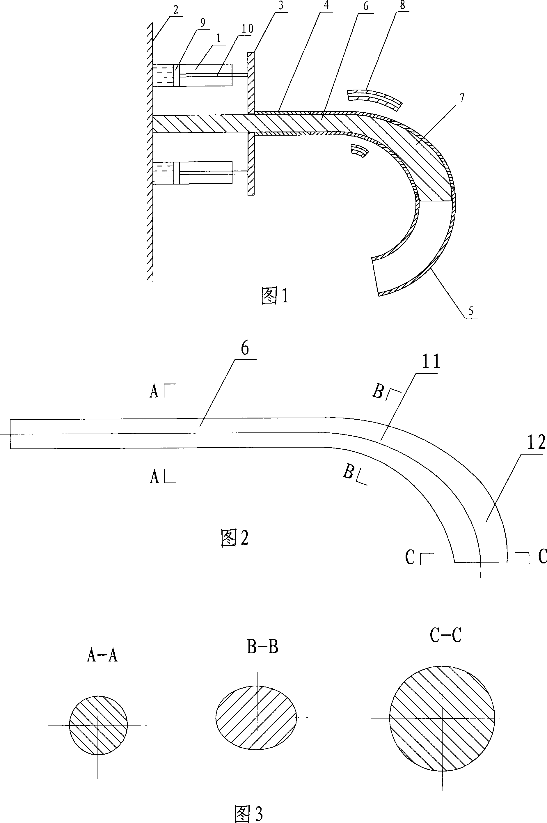
[0021] Step 1: Insert at least a section of the tube blank 4 from the end of the mandrel 6 of the horn mandrel to the rod body of the mandrel 6, and move the tube blank 4 along the rod body to the horn head 7 of the horn mandrel and approach it. The horn core head 7 of the horn mandrel; the end of the core rod 6 is passed through the middle of the push plate 3 and connected to the fixed end 2, so that the tube blank 4 is located on the side of the push plate 3 facing the horn core head 7 of the horn mandrel, And the periphery of the orifice of the tube blank 4 is abutted against the periphery of the through hole of the push plate 3;
[0022] Step 2: At least two symmetrically arranged propulsion cylinders 1 are connected to the propulsion plate 3 and the tube blank 4 is moved along the mandrel 6 to the horn core head 7 at...
Embodiment 2
[0027] The intermediate frequency induction heating in the present embodiment pushes the process of the elbow made of non-magnetic austenitic stainless steel:
[0028] Step 1: Insert at least a section of the tube blank 4 from the end of the mandrel 6 of the horn mandrel to the rod body of the mandrel 6, and move the tube blank 4 along the rod body to the horn head 7 of the horn mandrel and approach it. The horn core head 7 of the horn mandrel; the end of the core rod 6 is passed through the middle of the push plate 3 and connected to the fixed end 2, so that the tube blank 4 is located on the side of the push plate 3 facing the horn core head 7 of the horn mandrel, And the periphery of the orifice of the tube blank 4 is abutted against the periphery of the through hole of the push plate 3;
[0029] Step 2: At least two symmetrically arranged propulsion cylinders 1 are connected to the propulsion plate 3 and the tube blank 4 is moved along the core rod 6 to the horn core head ...
PUM
 Abstract
Description
Claims
Application Information
 - R&D
- Intellectual Property
- Life Sciences
- Materials
- Tech Scout
- Unparalleled Data Quality
- Higher Quality Content
- 60% Fewer Hallucinations
Browse by: Latest US Patents, China's latest patents, Technical Efficacy Thesaurus, Application Domain, Technology Topic, Popular Technical Reports.
© 2025 PatSnap. All rights reserved.Legal|Privacy policy|Modern Slavery Act Transparency Statement|Sitemap|About US| Contact US: help@patsnap.com