Electronic device fixed rack structure

A technology for electronic devices and fixing frames, which is applied to the rack/frame structure, support structure installation, support structure on hinges/pivots, etc., and can solve problems such as shaking, loosening of the knob tightening mechanism, and inconvenience

Inactive Publication Date: 2008-06-04
KINPO ELECTRONICS
View PDF3 Cites 10 Cited by
  • Summary
  • Abstract
  • Description
  • Claims
  • Application Information

AI Technical Summary

Problems solved by technology

However, in this type of fixing frame structure, the stability and rigidity of the moldable rod body structure are usually not very good, resulting in serious shaking problems during driving
In addition, the fixed frame structure in the form of pivoted rods often has the problem of loosening the knob tightening mechanism, and its operation is also inconvenient for the user to operate while driving, which is likely to cause a dangerous factor in the driving process.

Method used


Image

  • Electronic device fixed rack structure
  • Electronic device fixed rack structure
  • Electronic device fixed rack structure

Examples


Embodiment Construction

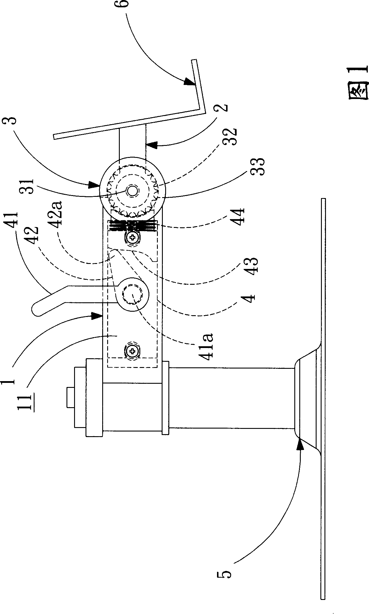
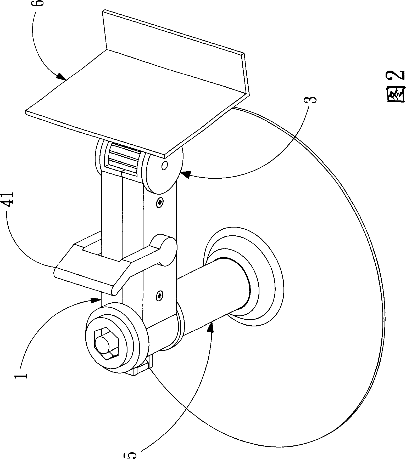
[0017] In order to obtain a clear expression of the structural features, component composition and desired effects of the present invention, the accompanying drawings are used to illustrate, so that those skilled in the art can understand the principles of the present invention. Referring to FIG. 1 and FIG. 2, FIG. 1 is a partial perspective and side view showing a specific embodiment of the electronic device fixing frame structure of the present invention, and FIG. 2 is a perspective view showing the specific embodiment of the present invention shown in FIG. 1. The structure of the electronic device fixing frame of the present invention is mainly a pivot connection between a first rod 1 and a second rod 2 through a first pivot device 3 , and the first pivot connection is selected through a locking device 4 The pivotable state or the non-pivotable state of the device 3 makes the first rod 1 and the second rod 2 correspondingly relatively pivotable or non-pivotable.
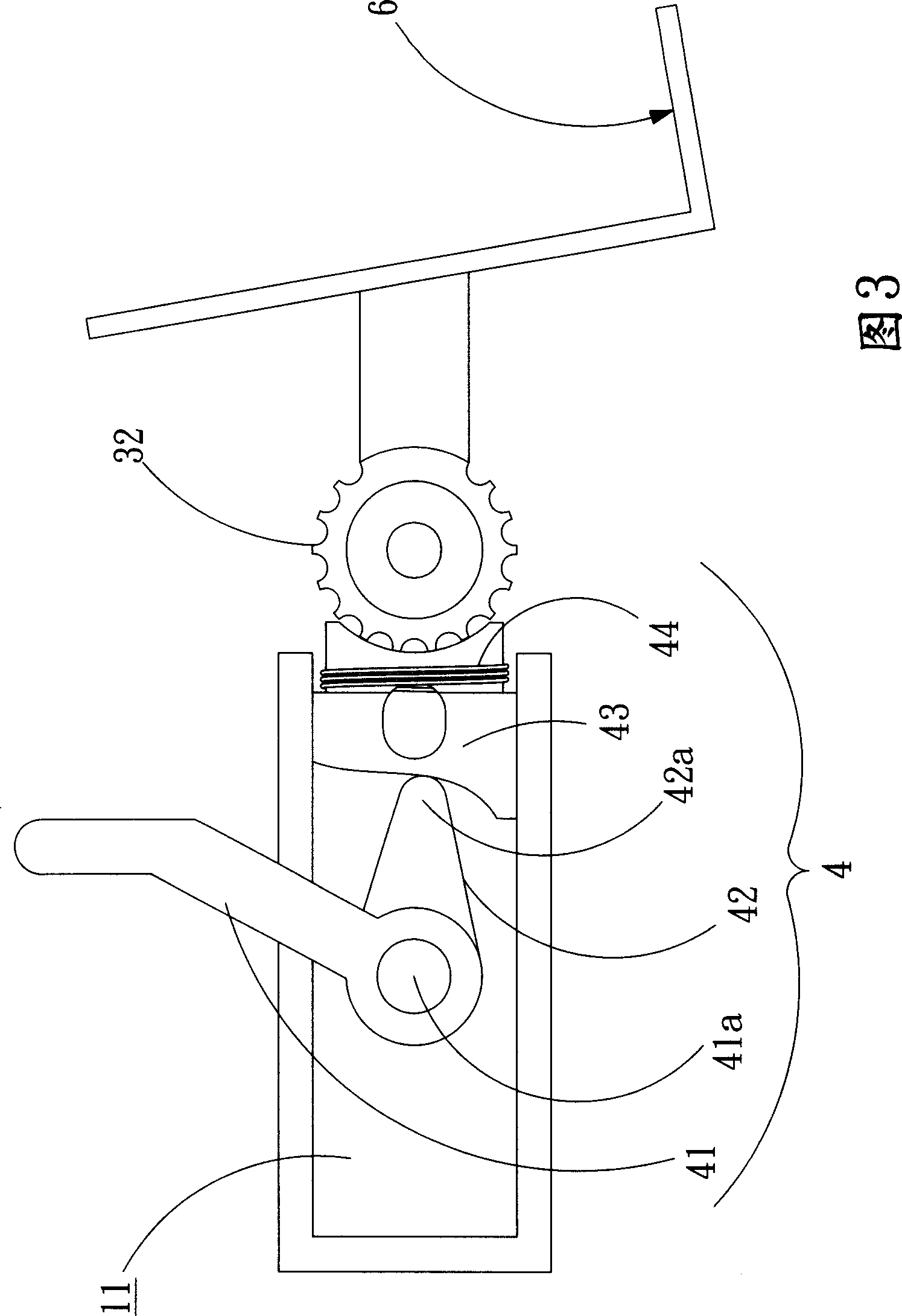
[0018] FI...


PUM


Abstract

The invention relates to a fixed frame for an electronic device, which comprises a plurality of members. The members are pivoted with each other respectively through a pivoting device, and at least a member is partially provided with a holding space which results in relative pivot rotation among the members. The fixed frame for the electronic device of the invention is also provided with a fixed lock device. A wrench bottom end in the fixed lock device is pivoted with a corresponding member corresponding to the holding space. A pivoting part of the wrench bottom end penetrates the member and is fixedly connected with a cam in the holding space. The holding space has a press block at a position corresponding to the cam in the manner of sliding, and the press block is restricted through a spring to closely contact the cam, therefore, the pivot rotation of the cam can select any status in which the sliding position of the press block is disconnected with a rotating shaft or the sliding position of the press block closely presses the rotating shaft.

Description

technical field [0001] The invention relates to an electronic device fixing frame structure, in particular to a pivot device and a locking device, so as to provide posture adjustment of the electronic device fixing frame structure. Background technique [0002] Existing portable electronic devices, such as mobile phones (mobile phones), PDAs, GPS (satellite navigation devices), etc., have convenient communication functions and have been widely accepted by the consumer market. Usually such portable electronic devices are installed on vehicles for the convenience of users when driving or riding in vehicles. [0003] In U.S. Patent No. 20060011795, No. 20050092877 and U.S. Patent Publication No. 6840487, several fixing frame structures are disclosed. It provides a fixed frame structure for portable electronic devices, which is composed of a shapeable rod structure or several rods pivotally connected, and the tightness of the pivot shaft is adjusted through the knob tightening ...

Claims


Application Information

Patent Timeline
Patent Type & Authority Applications(China)
IPC IPC(8): H05K7/16H05K7/18
Inventor 吕昆谚王瑞麟
Owner KINPO ELECTRONICS
Why Eureka
Try Eureka