Paper sheet separating mechanism
A separation mechanism and paper sheet technology, applied in pile separation, object separation, banknote processing equipment, etc., can solve the problems of abnormal size paper sheets that cannot be detected immediately, paper sheets jammed, and poor separation, etc. Prevents jamming or poor separation
- Summary
- Abstract
- Description
- Claims
- Application Information
AI Technical Summary
Problems solved by technology
Method used
Image

Examples
Embodiment 1
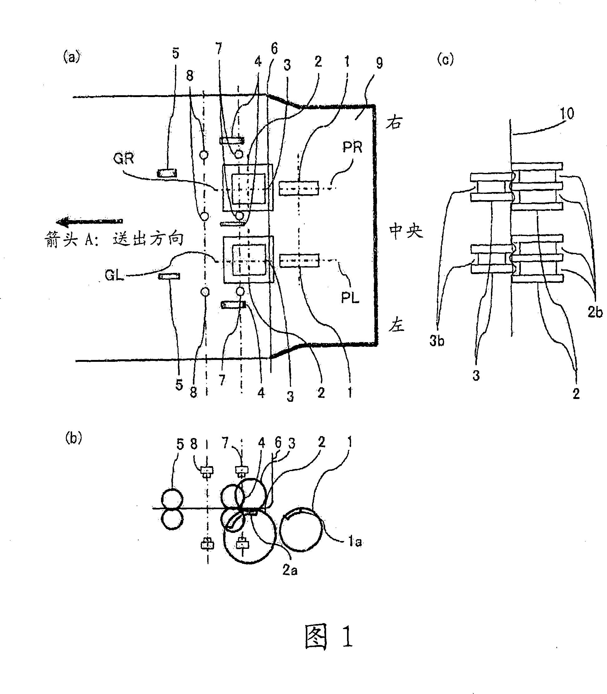
[0030] Fig. 1 is a diagram showing Embodiment 1 of the present invention, (a) is a plan view, (b) is a side view showing its main part, and (c) is a front view showing its main part.
[0031] In FIG. 1, 1 is a pickup roller, which is provided at the paper inlet 9 and has a high-friction member 1a on a part of the outer periphery. The high-friction member 1a has a paper sheet 10 for feeding and conveying the paper sheet. Kind of enough friction. A plurality of the pickup rollers 1 are arranged at predetermined intervals (in this embodiment, two are arranged on the left and right sides).
[0032] 2 is the delivery roller. Like the pickup roller 1, there is a high friction member 2a on a part of the outer circumference. The high friction member 2a has sufficient friction force for the paper sheet 10 to send and transport the paper sheet, and left and right. Two annular grooves 2b spanning the entire area in the circumferential direction are arranged side by side, respectively. The de...
Embodiment 2
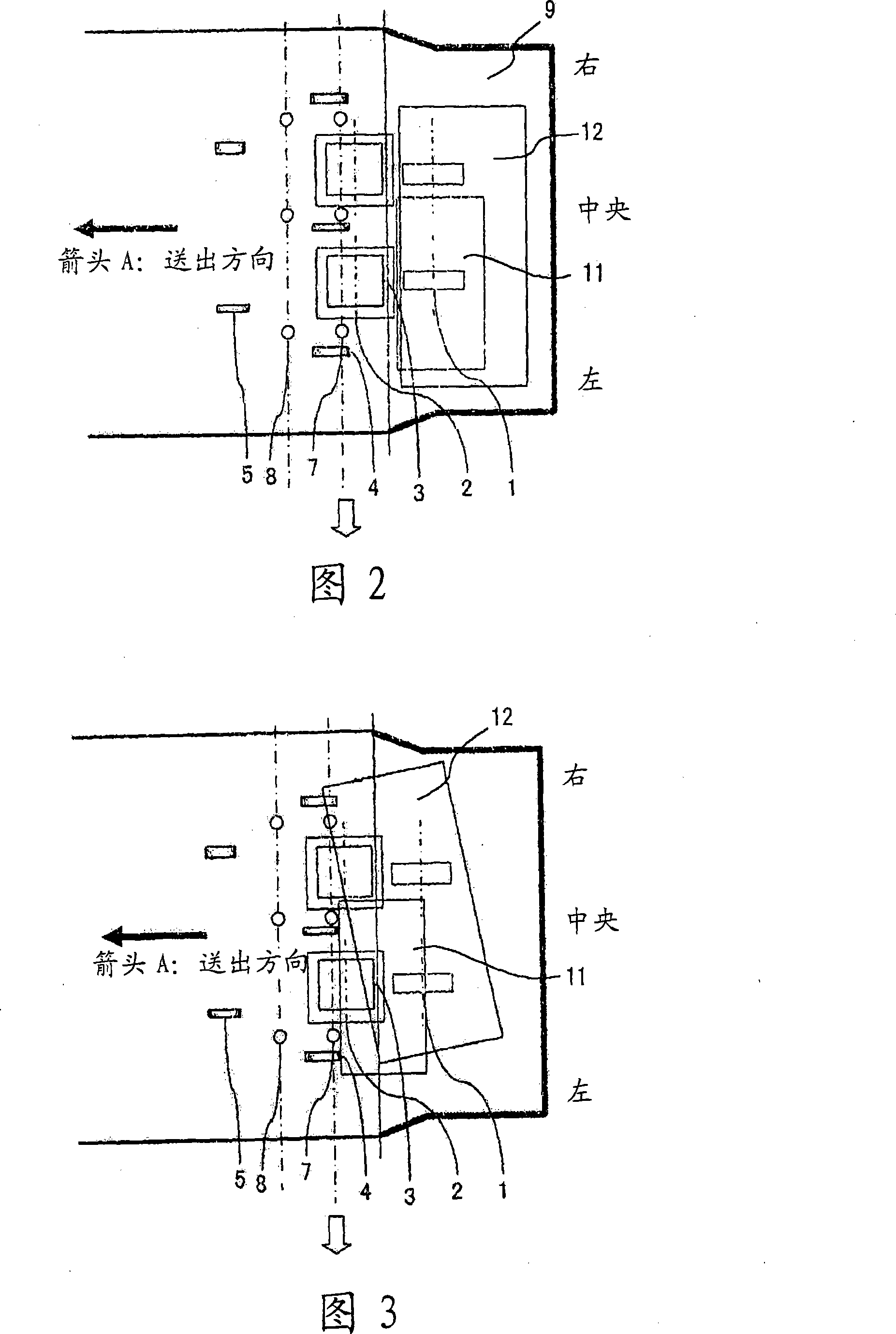
[0050] FIGS. 10 to 16 are diagrams for explaining the operation of the second embodiment of the present invention. In the first embodiment, it is determined that the order of the light-shielding state of the first row of sensors 7 and the order of the light-shielding state of the second row of sensors 8 are different An abnormality, however, in Example 2, when the left and right sensors in the first row or the second row block light and the central sensor does not block light, it is determined to be abnormal.
[0051] Fig. 10 is a diagram showing the state of inputting paper sheets, Fig. 11 is a diagram showing a state just after the paper sheets have passed through the door, Fig. 12 is a diagram showing a light-shielding state of the right side of the sensor 7, and Fig. 13 is a diagram showing The left side of the sensor 7 is a diagram showing the light-shielding state. FIG. 14 is a diagram showing the state of sending out a paper sheet with a crack in the center. FIG. 15 and FIG...
Embodiment 3
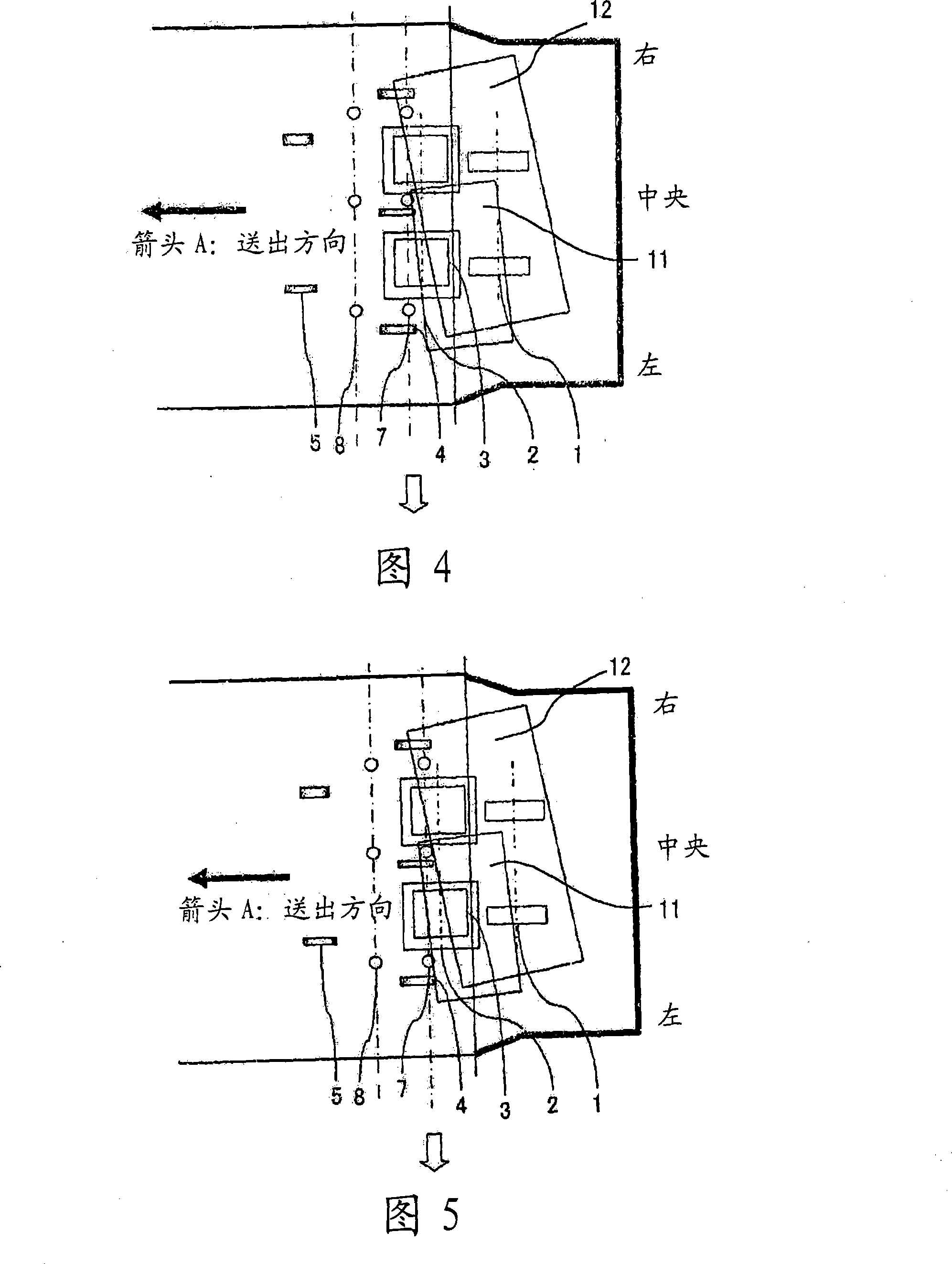
[0061] 17 and 18 are diagrams for explaining Embodiment 3 of the present invention, FIG. 17 is a diagram showing the central light-shielding state of the sensor 7, and FIG. 18 is a diagram showing that normal paper sheets and abnormal-sized paper sheets are being used. Figure of sensor output when page types are mixed.
[0062] The second embodiment is a case where the center of the sensor 7 or the sensor 8 is not shielded from light, and the third embodiment is an example in which it is determined that the sensor 7 or the sensor 8 in the center shields light earlier than the left and right sensors 7 as abnormal.
[0063] As shown in FIG. 17, when the normal paper sheets and the abnormally sized paper sheets are fed out from the set position in a mixed state, it is also considered that the center of the sensor 7 is blocked from light first. In this case, also when the normal paper sheets 12 are sent out, when the paper sheets 12 are sent out first, the light-shielding order of the...
PUM
 Abstract
Description
Claims
Application Information
 - Generate Ideas
- Intellectual Property
- Life Sciences
- Materials
- Tech Scout
- Unparalleled Data Quality
- Higher Quality Content
- 60% Fewer Hallucinations
Browse by: Latest US Patents, China's latest patents, Technical Efficacy Thesaurus, Application Domain, Technology Topic, Popular Technical Reports.
© 2025 PatSnap. All rights reserved.Legal|Privacy policy|Modern Slavery Act Transparency Statement|Sitemap|About US| Contact US: help@patsnap.com