
Armature of rotating electric machine and method of manufacturing the same

A technology for a rotating electrical machine and an armature, which is applied to the armature of a rotating electrical machine and its manufacturing field, can solve the problems such as the reduction of the accuracy of the shaft center of the cylinder hole, the inability to fully ensure the contact area between the shaft and the shaft hole, the lamination deviation, etc., and achieve rotational balance. Excellent and smooth thinning and drawing effect

Inactive Publication Date: 2010-09-15
MITSUBA CORP
View PDF4 Cites 0 Cited by
  • Summary
  • Abstract
  • Description
  • Claims
  • Application Information

AI Technical Summary

Problems solved by technology

[0006] On the other hand, since the core is formed by laminating a plurality of core pieces, lamination deviations occur anyway, and the deviations are also generated at the shaft hole, and the inner circumference of the shaft hole becomes stepped, or the diameter of the shaft hole becomes stepped. Axis accuracy is reduced
With such a structure, when the armature is formed by pressing a shaft without protrusions, since the lamination deviation directly affects the axis center accuracy of the shaft, there is a problem that the rotation balance is poor and surface runout occurs.
In addition, there is a possibility that the contact area between the shaft and the shaft hole cannot be sufficiently ensured. In this case, there is also a possibility that the fastening force between the core and the shaft is insufficient, causing problems. These are the problems that the present invention should solve.

Method used


Image

  • Armature of rotating electric machine and method of manufacturing the same
  • Armature of rotating electric machine and method of manufacturing the same
  • Armature of rotating electric machine and method of manufacturing the same

Examples


no. 2 approach

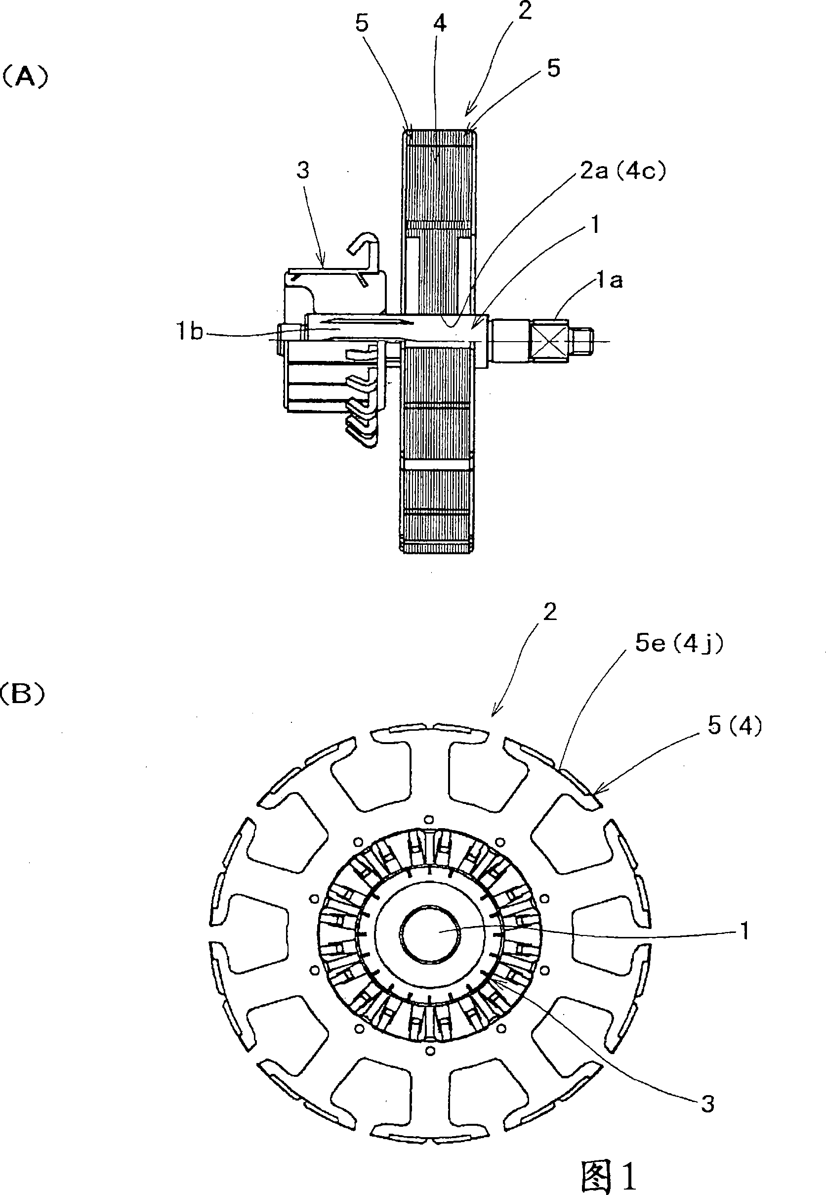
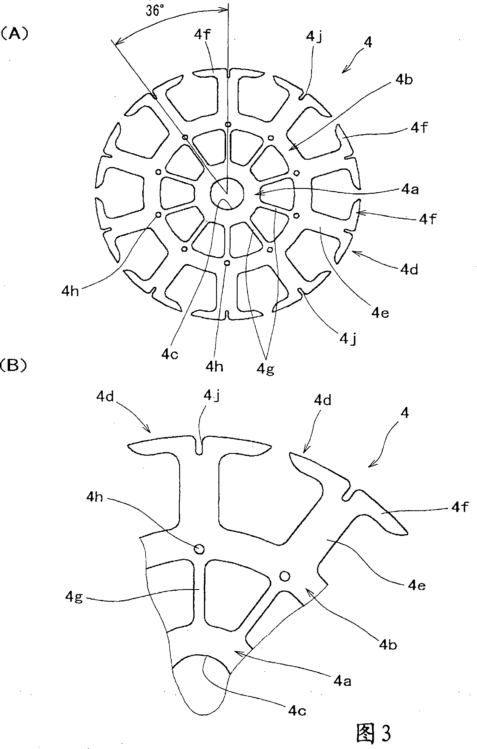
[0065] The second embodiment utilizes the main core 9 and the sub-core 10, and laminates a plurality of sub-cores 10 on both sides of the multi-piece main core 9 to form the core 8, which is the same as the previous embodiment. Part 9 has an inner diameter side ring portion 9a, an outer diameter side ring portion 9b, and 10 bridge pieces 9c connecting their circumferential rotation directions, and a sub-core member 10 has a ring portion 10a, and each core member 9,10 10 teeth 9d, 10b in the direction of circumferential rotation are formed on the outer periphery of the rim. Furthermore, in this structure, although the caulking portions 9e, 10c as an integrated mechanism for integrating the core members 9, 10 are formed on the outer diameter side of the bridge piece portion 9c, these caulking portions 9e, 10c are formed along the The middle portion of the teeth 9d, 10b adjacent in the circumferential rotation direction in the main core member outer diameter ring portion 9b and t...


PUM


Abstract

An armature of a rotating electric machine formed to provide excellent rotating balance. A plurality of auxiliary core materials (5) are laminated on both sides of a plurality of main core materials (4) by using the main and auxiliary core materials (4) and (5) formed of ring-shaped plate materials. These core materials (4) and (5) are formed integrally with each other by caulking their bosses with caulking parts (4h) and (5f) formed on the core materials so as to form a core (2). Ironing is applied to a shaft hole (2a) formed in the core (2) by using an ironing punch (7) before a complete-round motor shaft (1) is press-fitted thereinto.

Description

technical field [0001] The present invention belongs to the technical field of an armature constituting a rotating electric machine such as an electric device mounted on a vehicle and a method of manufacturing the same. Background technique [0002] In general, in this type of rotating electrical machine, the armature manufactured by fitting and supporting the shaft to the core of the wound coil has a structure in which a plurality of metal plates are punched out and manufactured. The formed ring-shaped plates are laminated through an integrated mechanism to constitute the core, and the shaft is pressed into the shaft hole formed in the core to fix the shaft in the core. In this case, it is necessary to fix the shaft in a state (integrated, fixed, fastened state) in which relative movement with respect to the core in the axial direction and in the axial circumferential direction is restricted. Therefore, a configuration has been proposed in which the outer diameter of the s...

Claims


Application Information

Patent Timeline
Patent Type & Authority Patents(China)
IPC IPC(8): H02K15/02H02K1/28
CPCH02K7/04H02K15/028H02K15/02H02K1/24H02K1/28Y10T29/49009Y10T29/49012
Inventor 木村正秋横尾次男细井启一寺田利一山崎洋一
Owner MITSUBA CORP
Learn More